
A plastic shredder handling food grade plastic waste is not simply a stronger version of an industrial scrap shredder. It is a hygiene-critical process machine that happens to cut plastic. The difference shows up in places most buyers never inspect during a factory audit: the radius of the weld seam where the cutting chamber wall meets the base plate, the grade of grease pumped into the rotor bearing, whether the screen cradle can be swung out and hosed down in eight minutes or has to be unbolted over two hours, and whether the plant can prove, on paper, which batch of post-consumer dairy crates went through the rotor last Tuesday afternoon. When recycled material is destined for food contact applications, every one of those details becomes part of the compliance file.
This guide explains how an Austrian-engineered plastic shredder is specified for food grade plastic waste, and why that particular design school has become the reference architecture for hygiene-sensitive recycling. Polyretec, a Wanplas factory, has manufactured plastic recycling equipment since 2010 and formalized the Polyretec brand in 2017, combining Austrian-origin shredding and washing technology with Chinese manufacturing capability. With more than one hundred completed project references, service coverage across more than fifty countries, and a team of over twenty-four engineers available for commissioning and remote assistance, Polyretec configures crushing and washing front ends for food grade PET bottle streams, food grade PP and PE crate and film streams, and industrial post-consumer waste. The engineering logic described in the following sections is the same logic our project engineers apply when they size a shredder for a specific waste stream.
The scope here is deliberately narrow and deep. We are looking at the shredding stage — the machine that turns bales, crates, drums, bottles and film rolls into a size-controlled feed that a washing line can actually clean. Everything downstream matters, and we cover the handoff, but the focus stays on the cutting chamber: the drive that turns the rotor, the blades that do the work, the screen that decides particle size, the guarding that keeps operators safe, and the hygienic detailing that lets a recycler sell into food contact markets rather than into low-value applications.
Why Food Grade Waste Changes the Shredder Specification
Food grade recycling imposes three requirements that ordinary size reduction does not: verifiable absence of cross-contamination, a documented and repeatable cleaning procedure, and full batch traceability from infeed bale to output flake. Each of these translates into concrete mechanical features, and each of them costs money that a general-purpose shredder specification simply does not carry.
Cross-contamination is a mechanical problem before it is a chemical one
Regulators approaching recycled plastic for food contact — the FDA in the United States through its no-objection letter process, and EFSA in the European Union through its opinions on recycling processes under the framework that also governs EU 10/2011 for plastic food contact materials — evaluate a recycling process as a whole, not a single machine. What they want to see is a process capable of reducing potential contaminants to a level of no concern, operated under conditions that are consistent and documented. The shredder contributes to that argument in two ways. First, it must not add contamination: no shedding of non-food-grade lubricant, no metal wear debris beyond what the downstream separation can remove, no paint flakes, no fragments of previously processed non-food streams. Second, it must be cleanable to a defined and repeatable standard, so that a changeover between an industrial stream and a food grade stream is a documented event rather than a hopeful one.
In practice, cross-contamination in a shredder comes from a small and predictable set of locations. Material lodges on horizontal ledges inside the hopper. It packs into the corner where a vertical wall meets the chamber floor at a sharp ninety-degree weld. It accumulates in the pocket behind the screen cradle where the screen frame overlaps the chamber wall. It hides under the ram plate of a hydraulic pusher when the ram is parked in the retracted position. It builds up in the gap between the rotor end disc and the chamber side wall, exactly where the shaft seal sits. Every one of these is a design decision, not an operating error, and every one of them can be engineered out at the drawing stage for a modest cost increase.
Cleanability drives the mechanical layout
A shredder that is nominally cleanable but takes six hours to clean will not, in real plant life, be cleaned. The economics of a recycling plant reward uptime, and any cleaning procedure that consumes a full shift will be shortened, skipped or performed superficially. Hygienic design therefore has a time dimension: a food grade shredder should permit full visual access to every internal surface within roughly thirty to sixty minutes using hand tools that live on the machine, and should permit high-pressure washdown without water entering bearings, the gearbox breather or the electrical enclosure.
This is why Austrian-engineered machines in this category are built with swing-out screen cradles on hinges rather than bolted screen frames, with hopper walls that hinge or lift away from the cutting chamber, with hydraulic ram plates that can be driven to a full-open service position, and with rotor end seals that are accessible from outside the chamber. None of these features improve throughput by a single kilogram per hour. All of them determine whether the plant can honestly claim a validated cleaning procedure.
Traceability is a data requirement with mechanical consequences
Batch traceability means being able to link an output big bag of flake back to a specific input consignment. At the shredding stage this requires the machine to record, at minimum, run start and stop times, motor load profile, screen aperture installed, blade set identity, and any fault or reversal event. Modern control systems handle the recording; the mechanical consequence is that the screen and blade set must be individually identifiable, and the machine must be genuinely empty between batches. A shredder that retains twenty kilograms of material in dead volume after the conveyor stops cannot support clean batch separation, no matter how good the software is.
| Design aspect | Standard industrial shredder | Food grade plastic waste shredder | Why the difference matters |
|---|---|---|---|
| Internal weld transitions | Square-cut welds, ground flush only where visible | Radiused transitions, typically 6 mm minimum radius, fully ground and continuous welds | Sharp internal corners retain material and resist washdown |
| Product contact surfaces | Painted carbon steel | Stainless steel 304 standard, 316L where chloride or acidic wash chemistry is present | Paint flakes are a physical contaminant; stainless resists pitting under repeated washdown |
| Screen access | Bolted frame, removed with lifting equipment | Hinged swing-out cradle, quick-release clamps, single-operator access | Cleaning frequency collapses if access requires a crane |
| Bearing lubricant | General-purpose lithium grease | Food-grade H1 lubricant on all points with any credible path to product | Incidental lubricant contact must be from an approved category |
| Dead volume after stop | Not specified | Quantified and minimized; typically under a few kilograms in the cutting chamber | Residual material defeats batch separation |
| Shaft seal design | Simple labyrinth or felt seal | Cleanable multi-stage seal with external grease relief and inspection access | The rotor end gap is the classic hidden contamination pocket |
| Documentation package | Operating manual, parts list | Material certificates for contact surfaces, surface finish records, cleaning validation protocol, blade and screen identification log | Auditors ask for the file, not for a factory tour |
| Changeover procedure | Informal | Written SOP with verification step and sign-off record | An undocumented changeover cannot be defended in an audit |
The table above is worth reading twice, because the cost difference between the two columns is far smaller than most buyers assume — typically a moderate premium on the shredder capital cost — while the difference in achievable output value is very large. A recycler producing flake that can enter food contact applications operates in a fundamentally different market from one producing flake for pipe backing layers or refuse sacks. The shredder specification is one of the cheaper places to buy access to that market.
What food grade does not mean at the shredding stage
It is equally important to be clear about what the shredder cannot deliver. A shredder does not decontaminate. It does not remove migrated substances from the polymer matrix, it does not sanitize, and it does not sort polymers. Any claim that a shredder makes material food grade is engineering nonsense. What the shredder does is preserve the possibility of food grade output by not introducing contamination and by producing a particle size distribution that allows the washing, separation and decontamination stages downstream to reach their rated performance. That is a supporting role, but it is a decisive one: a shredder that produces a wide, uncontrolled particle size distribution will cap the performance of every stage that follows it.
Austrian-Engineered Shredding Technology: What the Design School Means
When the recycling industry refers to Austrian technology in the context of shredders, it is referring to a coherent set of engineering choices developed for post-consumer plastic waste rather than to any single manufacturer. Polyretec incorporates this Austrian-origin design school into its cutting chamber, drive and feeding architecture, then manufactures it in China at a cost structure that makes it accessible to recyclers who would otherwise buy a compromise machine. Understanding the design school on its own terms is more useful than comparing supplier names, because the design choices are the thing that actually determines whether the machine survives ten years of dirty post-consumer material.
The five defining characteristics
The Austrian-engineered approach to plastic shredding rests on five interlocking decisions. Each one individually looks like a cost increase. Taken together they produce a machine with dramatically lower specific energy consumption, longer tool life and far better tolerance of contaminated feed than the high-speed, low-torque alternatives that dominate the cheap end of the market.
First, low rotor speed with very high torque. Austrian-origin single-shaft shredders for plastics typically run the rotor at roughly 60 to 120 rpm, an order of magnitude slower than a granulator rotor. Cutting force, not impact velocity, does the work. Low speed means less heat input into the polymer, less dust generation, less noise, and vastly reduced damage when a piece of tramp metal reaches the rotor. It also means the drive must deliver torque that a belt-driven high-speed rotor never needs to produce, which leads directly to the second characteristic.
Second, planetary gear direct drive or hydraulic drive. To generate that torque at that speed, the design school uses either a high-torque planetary gear reducer flange-mounted directly to the rotor shaft, or a hydraulic drive with a radial piston motor. The planetary direct drive eliminates the belt set entirely: no belt tensioning, no belt dust, no slip, no belt guard to clean. The hydraulic option trades some efficiency for extremely soft torque delivery and inherent overload protection, which suits the most contaminated feeds. Both approaches place the drive outside the cutting chamber, which is a hygienic advantage in its own right.
Third, hydraulic pusher feeding. A horizontal hydraulic ram, driven by a hydraulic cylinder, pushes material against the rotor at a controlled and adjustable pressure. This is the single most important feature for bulky, springy, low-bulk-density material such as film rolls, foamed trays, hollow crates and drums. Gravity feeding into a slow rotor simply does not work with these materials: they bridge, they bounce, and the rotor idles. The ram converts an erratic gravity feed into a stable, load-controlled feed, and the control system modulates ram pressure and travel against measured motor load. The practical result is that motor load sits in a narrow band around the target instead of oscillating between idle and stall, which is where most of the specific energy savings come from.
Fourth, V-shaped or U-shaped cutting chamber geometry with counter knives. The chamber profile is not a plain circular bore. A V-shaped chamber floor guides material toward the rotor and prevents it from resting on flat surfaces where it neither gets cut nor discharges. Counter knives are mounted at the chamber wall in a defined shear relationship with the rotor blades, and the cutting action is a true scissor shear rather than an impact fracture. Shear cutting at low speed produces clean-edged flake with a narrow particle size distribution and very little fine dust, which is exactly what a downstream washing line and pelletizing line want to receive.
Fifth, square indexable blades. The rotor carries square or rectangular blade inserts bolted to blade holders, each blade having four usable cutting edges. When one edge dulls, the operator loosens the bolt, rotates the blade ninety degrees and re-torques it. The same physical blade delivers four service lives before it is sent for regrinding or scrapped. Across a fleet of forty to sixty blades on a mid-size rotor, this is the difference between a tolerable and an intolerable tooling budget.
| Design feature | Typical parameter | Functional benefit | What is lost without it |
|---|---|---|---|
| Low rotor speed | 60–120 rpm depending on rotor diameter and material | Low heat input, low dust, low noise, tolerant of tramp metal | High-speed rotors melt film, generate fines and are destroyed by metal |
| Planetary gear direct drive | High-torque planetary reducer flanged to rotor shaft | No belt maintenance, compact footprint, full torque available at zero speed | Belt slip under load, belt dust in a hygienic zone, torque limited by belt friction |
| Hydraulic drive option | Radial piston motor with pressure-limited circuit | Inherent overload protection, infinitely variable speed, very soft start | Mechanical drives need electronic torque limiting and take shock loads |
| Hydraulic pusher ram | Adjustable pressure, load-following control, full retract for service | Stable feed of bulky low-density material, motor load held in a narrow band | Bridging, rotor idling, throughput collapse on film and hollow parts |
| V-shaped cutting chamber | Guided chamber floor, no horizontal ledges | Material always presented to the rotor, chamber self-clears | Material rests on flat surfaces, dead volume, contamination pockets |
| Counter knife shear cutting | Adjustable rotor-to-counter-knife clearance | Clean shear cut, narrow particle size distribution, minimal fines | Impact fracture produces dust, fluff and a wide size spread |
| Square indexable blades | Four usable edges per blade insert | Four service lives per blade, ninety-second index operation | Single-edge blades quadruple tooling cost per operating hour |
| Adjustable rotor-to-screen clearance | Typically set between 0.3 and 1.0 mm | Compensates blade wear, holds particle size and throughput stable | Growing clearance means longer strips, more recirculation, rising energy per ton |
| Overload reversal protection | Automatic reverse-and-retry on torque threshold | Clears jams without operator entry into the chamber | Manual jam clearing is the highest-risk task on the machine |
| Metal and foreign object protection | Magnetic separation plus inductive metal detection upstream | Protects blades, prevents metal contamination of food grade flake | One steel bolt can destroy a full blade set and a screen |
Why low speed and high torque matter specifically for food grade streams
Food grade waste streams have a characteristic that industrial scrap does not: they arrive with residues. A post-consumer dairy crate carries dried milk solids. A beverage bottle bale carries sugar residue and liquid. Food grade film carries fat, protein and starch. When these materials meet a high-speed rotor, frictional heating softens the polymer and bakes the organic residue onto the flake surface and onto the cutting tools. Baked-on organic soil is dramatically harder to remove in a friction washer than fresh soil, and it is the single most common reason why a washing line fails to hit its target on organic load.
A low-speed shear cut keeps the polymer below its softening range, keeps residues loose rather than fused, and hands the washing line a far easier job. This is a real, measurable process advantage and it is why the Austrian-engineered route dominates in food grade applications rather than in general industrial scrap, where high-speed granulation remains perfectly acceptable.
The Austrian route is a technology choice, not a nameplate
One clarification is worth making explicitly, because it comes up in almost every technical conversation with a buyer. Austrian-engineered shredding technology describes a cutting geometry, a drive architecture and a feeding philosophy. It does not describe where a specific casting was poured. Polyretec applies these design principles — the V-chamber, the low-speed high-torque planetary drive, the hydraulic ram, the indexable blade system, the adjustable screen clearance — and manufactures the resulting machine under its own quality system, using its own machining and assembly capability, with material certificates for the food contact surfaces. A buyer evaluating machines should therefore evaluate the parameters in Table 2, one by one, against the offered specification. That is a comparison that can be verified. A comparison based on country of origin claims is not.
Hygienic Design of the Cutting Chamber
Hygienic design in a food grade plastic shredder follows the same logic as hygienic design in food processing equipment, adapted to a machine that is deliberately abrasive. The objective is simple to state and demanding to achieve: every surface that material touches must be visible, reachable and cleanable, and no surface may retain material when the machine stops.
Geometry rules that eliminate dead corners
The first rule is that there are no horizontal ledges anywhere inside the material path. Every internal surface is either steeply inclined toward the rotor or vertical. Where a support gusset would create a shelf, the gusset is placed on the outside of the chamber wall. Where a bolt head would protrude into the chamber, the fastener is countersunk or replaced by a weld.
The second rule is that internal corners are radiused. A ninety-degree internal weld is a material trap, and no amount of pressure washing reliably clears it. A radius of at least 6 mm at every internal transition — chamber wall to floor, chamber wall to end plate, hopper wall to chamber flange — allows a water jet to sweep the corner clean. Welds in the material path are continuous rather than stitched, and they are ground and polished rather than left as-deposited, because a rough weld bead is functionally identical to a ledge at the microscopic scale where organic residue clings.
The third rule is that removable components can actually be removed by one person in normal working clothes. The screen cradle swings out on a hinge and is held by quick-release clamps. The hopper section that sits above the cutting chamber lifts or hinges clear. The hydraulic ram plate can be driven to a full-open service position that exposes the chamber floor behind it. Access doors are interlocked so the rotor cannot be energized while they are open, which is a safety requirement that also happens to make frequent access practical.
Contact material selection
Contact surface material is the question buyers ask most often and specify least precisely. The engineering answer depends on what the surface actually touches and under what chemistry.
| Component | Recommended material | Rationale | When to upgrade |
|---|---|---|---|
| Hopper interior and chute walls | Stainless steel 304, 2B or better finish | Corrosion resistance under repeated washdown, no coating to flake off | 316L where caustic or chloride-bearing wash water contacts the surface |
| Cutting chamber walls and floor | Stainless steel 304 with abrasion-resistant liner plates in high-wear zones | Balances hygiene against the abrasive reality of post-consumer feed | 316L in coastal plants or where seawater-derived contamination is present |
| Rotor body | Alloy steel, machined and finished; stainless cladding available | Structural duty dominates; surface is continuously scoured by material | Stainless cladding for wet shredding of PET bottle streams |
| Blade inserts and counter knives | Tool steel, hardened; see the tooling section | Hardness governs; these are consumable, inspected and replaced | Powder metallurgy grades for abrasive filled or contaminated streams |
| Screen | Stainless steel 304 or hardened perforated plate | Must resist both abrasion and washdown chemistry | 316L where the screen sits in a wet crushing circuit |
| Fasteners in the material path | Stainless steel, countersunk or capped | Prevents galvanic corrosion products and eliminates protruding traps | Always stainless in a food grade machine |
| Seals and gaskets | Food contact compliant elastomer, light color for visual detection | Fragments must be detectable if a seal fails | Metal-detectable elastomer where a metal detector guards the outfeed |
| Bearing and gearbox lubricant | Food-grade H1 lubricant on all points with a credible path to product | Incidental contact must come from an approved lubricant category | Full H1 changeover including the gearbox for certified food grade lines |
Lubrication policy
Lubricant policy deserves its own paragraph because it is frequently mishandled. The correct approach is a written lubrication schedule that identifies every lubrication point on the machine, classifies each point by whether a credible contamination path to product exists, and assigns a food-grade H1 lubricant to every point in that category. Rotor end bearings, ram guide rails, screen cradle hinges and any grease point above the material path all fall inside the boundary. The gearbox is a judgment call: on a fully certified food grade line it is normal to convert the gearbox to a food-grade H1 fill as well, accepting a modest reduction in oil change interval in exchange for eliminating the argument entirely. Grease relief must be routed outward and away from the chamber, and the color of the specified grease should differ from the color of any non-food-grade lubricant kept in the plant, so a wrong-grease event is visible on inspection.
Cleaning validation logic
A hygienic machine still needs a validated cleaning procedure. The logic that regulators and auditors respond to is straightforward: define the worst-case soil, define the cleaning procedure, execute it, then measure whether the defined acceptance criterion is met, and repeat enough times to show the result is reproducible. For a shredder, the worst-case soil is usually a high-fat, high-protein residue from a dairy or meat packaging stream, and the acceptance criteria are typically visual cleanliness under adequate lighting at defined inspection points, plus a surface swab result where the plant’s quality system requires one. The procedure should be timed, the inspection points should be photographed and listed, and the record should be signed. This is documentation work, not engineering work, but the machine must be designed to make it achievable — which returns us to hinges, radii and access.
Regulatory framing without overclaiming
It is worth restating how the regulatory framework actually applies, because equipment marketing often blurs it. In the European Union, a recycling process intended to produce plastics for food contact is assessed as a process; EFSA issues scientific opinions on submitted recycling processes, and the resulting material is used within the general framework for plastic food contact materials, of which EU 10/2011 is the central instrument. In the United States, a recycler typically seeks a no-objection letter from the FDA for a defined process operated within defined conditions. In both systems, approval attaches to a described process with defined input specifications and defined operating parameters. A shredder is a component of that process. It can be specified so that it supports the application — hygienic design, documented cleaning, controlled inputs, batch records — and it can be specified so that it undermines the application. What it cannot do is carry an approval of its own. Equipment suppliers who imply otherwise are describing something that does not exist.
Single-Shaft, Twin-Shaft and Heavy-Duty Granulator
Three machine classes cover essentially all plastic size reduction duty, and choosing between them is the most consequential decision in the whole specification. The three are not competitors so much as different tools: a single-shaft shredder, a twin-shaft shredder, and a heavy-duty granulator. Many food grade lines use two of them in series.
The single-shaft shredder
A single-shaft shredder has one rotor carrying indexable blades, one or more stationary counter knives, a hydraulic pusher ram and a screen beneath the rotor that determines discharge particle size. It runs slowly, produces a controlled and reasonably uniform output, and can be tuned across a wide particle size range simply by changing the screen. It is the standard first-stage machine for film, bags, woven sacks, crates, drums, purgings and bottle bales, and it is the machine class most closely associated with the Austrian-engineered design school.
Its limitation is infeed size and shape: very large rigid objects, thick-walled parts and heavily contaminated bulky waste can overwhelm a single rotor, and the ram cannot present material to the rotor if the material physically will not fit in the chamber.
The twin-shaft shredder
A twin-shaft shredder uses two counter-rotating shafts with interleaved cutter discs, running at different speeds to create a tearing and drawing action. There is no ram and usually no screen: material is drawn in by the shafts themselves. Twin-shaft machines accept enormous and awkward infeed — whole intermediate bulk containers, pallets, wire-bound bales, thick-walled drums — and reduce them to coarse pieces, typically in the range of 50 to 200 mm.
Because there is no screen, the output particle size distribution is wide, which is why twin-shaft shredders in plastic recycling are almost always a pre-shredder feeding a single-shaft shredder rather than a standalone solution. Their strength is destruction of bulky items and tolerance of gross contamination; their weakness is particle size control.
The heavy-duty granulator
A heavy-duty granulator runs a high-speed rotor, typically several hundred rpm, with fly knives shearing against bed knives and a fine screen beneath. It produces small, uniform flake — often in the 6 to 20 mm range — which is exactly what a washing line and a pelletizing line want. It is the standard second-stage machine, and in PET bottle washing lines it is routinely configured as a wet crusher, with process water injected into the cutting chamber to suppress heat, suppress dust and start the washing action at the moment of cutting.
Its weakness is that it is intolerant. Tramp metal wrecks a granulator rotor. Bulky material bridges above it. Contaminated abrasive feed destroys its knives quickly. A granulator belongs downstream of a shredder and downstream of metal separation, not at the head of the line.
| Criterion | Single-shaft shredder | Twin-shaft shredder | Heavy-duty granulator |
|---|---|---|---|
| Typical waste suited | Film, bags, woven sacks, crates, bottles, drums, purgings, baled material | Bulk containers, pallets, wire-bound bales, thick-wall drums, mixed bulky waste | Pre-shredded flake, bottle bodies, rigid regrind, sprues and trims |
| Maximum infeed size | Limited by hopper opening, typically up to about 1500 mm in one dimension | Very large, effectively limited by the crane or loader | Small, typically under 300 mm and free of metal |
| Typical output particle size | 15–80 mm, set by screen aperture | 50–200 mm, no screen, wide distribution | 6–20 mm, set by screen aperture, narrow distribution |
| Rotor speed | 60–120 rpm | 10–30 rpm per shaft, differential speed between shafts | 300–700 rpm depending on rotor diameter |
| Torque character | Very high torque, moderate speed | Extremely high torque, very low speed | Low torque, high speed, energy stored in flywheel effect |
| Specific energy, film and soft waste | Approximately 30–60 kWh per ton | Approximately 15–35 kWh per ton for coarse reduction only | Approximately 45–90 kWh per ton, higher on film |
| Specific energy, rigid waste | Approximately 25–50 kWh per ton | Approximately 12–30 kWh per ton | Approximately 30–60 kWh per ton |
| Noise level at operator position | Generally below 85 dB(A) with standard enclosure | Generally below 85 dB(A), impulsive noise on hard objects | Typically the loudest of the three; enclosure and acoustic hood usually required |
| Dust generation | Low, shear cutting at low speed | Low, tearing action | High in dry operation; low when configured as a wet crusher |
| Tolerance of tramp metal | Good, with reversal protection and indexable blades | Excellent | Poor; metal separation upstream is mandatory |
| Blade change frequency | Moderate; index rather than replace for three of four cycles | Low; cutter discs are robust and long-lived | High on abrasive feed; knives require frequent regrinding |
| Hygienic design difficulty | Moderate; ram and screen cradle need attention | Higher; interleaved discs are hard to clean fully | Moderate; simple chamber, but fine screens trap material |
| Role in a food grade line | Primary size reduction, most common single machine | Pre-shredder ahead of a single-shaft machine | Wet crushing stage immediately before or within the washing line |
| Relative capital cost | Medium to High | High to Very High | Low to Medium |
Typical configurations by stream
For a food grade PET bottle washing line, the standard configuration is a bale opener and pre-sorting station, then a heavy-duty granulator configured as a wet crusher, feeding directly into friction washing. A single-shaft shredder is added when the input includes large containers, drums or heavily compacted bales that the wet crusher cannot handle safely.
For a food grade PP and PE crate, drum and rigid packaging stream, the standard configuration is a single-shaft shredder producing 30 to 60 mm pieces, then metal separation, then a wet granulator producing 10 to 15 mm flake into the washing line.
For a food grade film stream — bread bags, produce bags, food grade stretch and shrink film — the standard configuration is a single-shaft shredder with a 40 to 80 mm screen feeding directly into a wet friction washer, with no granulation stage at all, because film does not need to be reduced further and granulating it wastes energy while generating fines.
Drive Architecture: Low Speed, High Torque, Hydraulic Feeding
The drive is where the Austrian-engineered route separates most clearly from commodity machine design, and it is where buyers most often accept a downgrade without realizing what they have given up. Three architectures dominate: belt drive with a flywheel, planetary gear direct drive, and hydraulic drive.
Belt drive with flywheel
The cheapest architecture uses a standard induction motor driving a heavy flywheel through V-belts, with a gear reducer between flywheel and rotor. Energy stored in the flywheel carries the rotor through momentary load peaks. It works, it is inexpensive, and it is genuinely adequate for clean, homogeneous industrial scrap.
Its drawbacks in a food grade context are specific. Belts slip under sustained high torque, and slip means heat, dust and unpredictable rotor speed. The belt guard is a cleaning liability in a hygienic zone. Available torque is capped by belt friction, so the machine stalls where a direct-drive machine would keep cutting. And the flywheel means the rotor cannot stop quickly, which complicates safety interlocking on access doors.
Planetary gear direct drive
A high-torque planetary reducer flange-mounted to the rotor shaft eliminates belts entirely. Full rated torque is available from zero speed, so the machine starts under load without difficulty. The drive train is compact, sealed and located outside the cutting chamber. Speed is set by the reducer ratio and, where a variable frequency drive is fitted, can be trimmed to match material behavior. Efficiency is high, typically well above ninety percent through the reducer, which shows up directly in the specific energy figure.
The trade-off is that overload protection must be provided electronically and mechanically rather than by belt slip: the control system monitors motor current, reverses the rotor on a defined torque threshold, retries a set number of times, and trips to a fault state if the obstruction persists. This is a solved problem, and the reversal logic is one of the features buyers should test during factory acceptance.
Hydraulic drive
A hydraulic drive uses an electric motor driving a pump, with a radial piston hydraulic motor turning the rotor. Torque is limited by circuit pressure, which means overload protection is intrinsic: when the rotor cannot turn, pressure rises to the relief setting and nothing breaks. Speed is infinitely variable, reversal is instantaneous, and torque delivery is extremely soft, which is valuable on feeds containing occasional very hard objects.
The cost is efficiency. A hydraulic drive typically loses more energy than a planetary reducer, which raises specific energy consumption by a meaningful margin, and it adds a hydraulic circuit that must be maintained, cooled and kept clean. In a food grade zone, the hydraulic circuit also raises the question of oil selection, which is answered by using a food-grade H1 hydraulic fluid where any credible leak path to product exists.
| Attribute | Belt drive with flywheel | Planetary gear direct drive | Hydraulic drive |
|---|---|---|---|
| Torque at zero speed | Limited by belt friction | Full rated torque available | Full rated torque, pressure limited |
| Overload protection | Belt slip, uncontrolled | Electronic torque limit with automatic reversal | Intrinsic via pressure relief |
| Drive efficiency | Moderate; belt losses plus slip losses | High; typically above ninety percent through the reducer | Lower; pump and motor losses accumulate |
| Speed control | Fixed unless a frequency converter is added | Fixed ratio, trimmable with a frequency converter | Infinitely variable |
| Reversal response | Slow; flywheel inertia must be overcome | Fast | Immediate |
| Maintenance burden | Belt tension, belt replacement, alignment | Oil change on the reducer, coupling inspection | Filter changes, oil condition, cooler, hose inspection |
| Hygienic suitability | Poor; belt dust and a guard that is hard to clean | Good; sealed unit outside the material zone | Good, provided food-grade H1 fluid is used where leak paths exist |
| Noise contribution | Moderate; belt and flywheel noise | Low | Moderate; pump noise, usually located remotely |
| Relative cost | Low | Medium to High | High |
| Best suited to | Clean homogeneous industrial scrap | Food grade and post-consumer streams needing consistent output | Heavily contaminated feed with unpredictable hard objects |
The hydraulic pusher ram and why feed control is a drive question
The ram is often described as a feeding device, but it is more accurate to think of it as part of the drive control loop. The control system reads main motor load continuously. When load falls below the target band, the ram advances and pressure increases, pushing more material into the rotor. When load approaches the upper limit, the ram holds or retracts slightly. The loop keeps the rotor working at a high, stable load factor.
This matters enormously for energy. A shredder running at forty percent average load factor with wide swings consumes far more energy per ton than the same machine held at seventy-five to eighty-five percent with narrow swings, because fixed losses — windage, bearing friction, gearbox churning, control power — are amortized over a much larger throughput. Ram control is the mechanism that makes a high load factor achievable on materials that would otherwise feed erratically.
Ram design details worth specifying: stroke long enough to sweep the full chamber floor; a ram face profile that matches the chamber geometry so no wedge gap remains at full extension; a full-retract service position that exposes the chamber floor for cleaning; guide rails outside the material zone or protected by wipers; and adjustable pressure so the operator can reduce force on delicate film and increase it on dense rigid feed.
The Cutting Tool System: Material, Geometry and Service Life
Blades are the largest single consumable cost in a shredder and the dominant influence on output quality. Once a blade edge dulls, cutting turns into tearing, energy consumption climbs, particle size becomes irregular, fines increase, and the motor load pattern becomes ragged. Tool management is therefore not a maintenance afterthought; it is a process control activity.
Blade material and hardness
Plastic shredder blades are made from tool steels selected for a balance of hardness, toughness and wear resistance. Cold work tool steels of the high-carbon, high-chromium family — the grades commonly designated D2 in the American system and SKD-11 in the Japanese system, which are broadly equivalent — are the workhorse choice, typically heat treated to 58 to 62 HRC. They hold an edge well, resist abrasive wear, and are economical to regrind.
For abrasive feeds — material carrying sand, glass fines, mineral filler or ash from agricultural film — powder metallurgy high speed steel grades offer substantially longer edge life at higher cost and lower impact toughness. For feeds with a real risk of tramp metal, a tougher grade at slightly lower hardness, in the 55 to 58 HRC range, is often the better economic choice because it chips less and can be reground rather than scrapped.
| Blade material family | Typical hardness | Wear resistance | Impact toughness | Best suited to | Relative tooling cost |
|---|---|---|---|---|---|
| High-carbon high-chromium cold work tool steel, D2 or SKD-11 type | 58–62 HRC | High | Moderate | General food grade PP, PE, PET streams; the default choice | Medium |
| Same family at reduced hardness | 55–58 HRC | Moderate | Higher | Streams with occasional tramp metal or hard foreign objects | Medium |
| Powder metallurgy high speed steel | 60–64 HRC | Very high | Lower | Abrasive feed: agricultural film with soil, mineral-filled material | High to Very High |
| Tungsten carbide tipped or faced | Effective hardness well above tool steel | Extremely high | Low | Highly abrasive niche duty; requires very clean, metal-free feed | Premium |
| Surface-treated tool steel with hard coating | Base 58–62 HRC plus coating | High to very high on the coated face | As base steel | Extending life on moderately abrasive food grade streams | High |
Blade geometry and rotor layout
Blade inserts on an Austrian-engineered rotor are square or rectangular, bolted into machined pockets on blade holders, presenting one edge to the material at a time. Four edges per insert is the standard, and rotating a blade to a fresh edge is a two-minute operation per blade with the correct torque wrench.
Layout on the rotor is either helical or staggered. A helical layout places blades along a spiral so that cutting is progressive: one blade enters the cut as another leaves, producing near-continuous torque demand, low vibration and low noise. A staggered or row layout places blades in discrete rows, which is mechanically simpler and slightly cheaper but produces a pulsing load. For food grade lines running continuously, the helical layout is worth the modest premium because the smoother load pattern extends bearing and gearbox life and reduces noise at the operator position.
Counter knives sit at the chamber wall, and their relationship to the rotor blades defines the shear. Clearance between rotor blade tip and counter knife edge is the critical adjustment: too tight and the tools contact each other, chipping both; too loose and the material folds rather than shears, producing long tails, poor screen passage and rising energy consumption. Typical clearance is a few tenths of a millimeter, checked with a feeler gauge at several positions across the rotor width and reset whenever blades are indexed.
Rotor-to-screen clearance
A second clearance matters just as much and is checked less often: the gap between the rotor blade tips and the screen surface, typically set between 0.3 and 1.0 mm. A tight clearance in the lower part of that range gives cleaner cutting of the material trapped against the screen, less recirculation and a more uniform particle size, at the cost of more sensitivity to hard foreign objects. A wider clearance is more forgiving but allows material to ride around the chamber without being cut, which shows up as reduced throughput and elevated energy per ton.
Because blade tips wear, this clearance grows over the life of a blade set. A machine that produced 25 mm flake at 1000 kg per hour when commissioned may be producing irregular 35 mm strips at 780 kg per hour six months later, purely from clearance growth, with the operator blaming the material. Machines that permit clearance adjustment — through shimming the counter knife, adjustable blade holders, or an adjustable screen cradle position — allow the process to be restored in an hour rather than requiring a full blade change.
Blade life and the economics of indexing
Blade life varies more than any other consumable figure in a recycling plant, because it depends almost entirely on what is in the feed rather than on the machine. A realistic planning range for a single-shaft shredder cutting food grade plastic waste is 300 to 1500 operating hours per cutting edge. Clean, sorted, indoor-generated food grade PP crates sit at the top of that range. Post-consumer agricultural film carrying soil and grit sits at the bottom, and can sit below it.
| Waste stream | Indicative edge life | Dominant wear mechanism | Practical countermeasure |
|---|---|---|---|
| Food grade PP and PE crates, trays, closures, clean industrial returns | 1000–1500 hours | Gradual abrasive rounding of the edge | Standard tool steel; index on a scheduled interval |
| Food grade PET bottle bales, sorted, label and cap present | 700–1200 hours | Abrasion plus occasional impact from closures and rings | Standard tool steel; magnetic separation upstream |
| Food grade film: bread bags, produce bags, clean shrink film | 800–1400 hours | Edge polishing and slow rounding, low impact | Standard tool steel; keep clearance tight for clean shear |
| Post-consumer mixed rigid packaging | 500–900 hours | Abrasion plus impact from foreign objects | Tougher grade at slightly lower hardness; robust metal detection |
| Agricultural film with soil and grit | 300–600 hours | Severe three-body abrasion from mineral particles | Powder metallurgy grade; pre-cleaning or dry shaking upstream |
| Woven sacks and big bags with residue | 400–800 hours | Abrasion plus fiber wrapping at the shaft ends | Anti-wrap discs at rotor ends; scheduled shaft-end inspection |
| Mineral-filled or heavily pigmented rigid material | 350–700 hours | Abrasion from filler particles | Powder metallurgy or coated blades; accept shorter interval |
The indexing economics follow directly. With four edges per insert, a blade set that delivers 1000 hours per edge delivers 4000 operating hours before the inserts leave the machine — roughly a full production year on a two-shift operation. Regrinding recovers a further one to two full sets of edges from most inserts, depending on how deeply the worn edge was damaged, before the insert dimension falls outside the tolerance the blade holder can accommodate. A disciplined plant tracks each insert by position number, records index events, and sends inserts for regrinding in complete sets so that all edges on the rotor are at the same condition. Mixing fresh and worn inserts on one rotor guarantees uneven load, poor particle size control and accelerated wear on the fresh tools.
Scrap criteria
Inserts should be scrapped rather than reground when any of the following is true: a chip extends deeper than the available regrind allowance; a crack is visible under magnification anywhere on the insert; the insert thickness after regrinding falls below the minimum that lets the blade holder clamp securely; or the mounting hole or seating face has deformed. These are inspection criteria that any trained maintenance technician can apply, and writing them into the maintenance procedure prevents the common failure mode in which a marginal insert is refitted, fails in service, and takes a blade holder and a screen with it.
Screen Aperture and Particle Size Control
The screen beneath the rotor is the cheapest component in the machine and the one that most directly determines what the rest of the plant experiences. Material circulates in the cutting chamber until it is small enough to pass a screen hole; the aperture therefore sets the upper bound on particle size, and indirectly sets throughput, energy consumption, fines generation and the workload of every downstream stage.
How aperture translates into actual particle size
A common misunderstanding is that a 40 mm screen produces 40 mm flake. It does not. Screen holes are round, and plastic pieces are irregular and often elongated. A piece passes when its smallest cross-section fits the hole, which means a 40 mm screen readily passes strips 40 mm wide and 120 mm long. In practice, the characteristic particle dimension from a round-hole screen is roughly 0.6 to 0.8 times the aperture for rigid material that fractures into blocky pieces, and considerably more elongated for film and sheet, which tend to pass as ribbons.
This is why film lines routinely use larger apertures than intuition suggests. Reducing film to genuinely small pieces requires many passes through the cutting zone, which consumes energy, generates heat and produces fines, while delivering no benefit at all to a friction washer that handles 60 mm film fragments perfectly well.
| Screen aperture | Typical rigid particle size | Typical film fragment size | Relative throughput index | Relative specific energy | Fines generation | Best downstream use |
|---|---|---|---|---|---|---|
| 20 mm | 12–18 mm blocky flake | Not recommended for film; heavy recirculation | 0.55 | Very High | High | Direct feed to a pelletizing line without an intermediate granulator |
| 30 mm | 18–26 mm flake | 25–70 mm ribbons | 0.72 | High | Moderate to high | Rigid PP and PE washing lines where no second-stage granulator is fitted |
| 40 mm | 25–34 mm flake | 35–90 mm ribbons | 0.85 | Medium | Moderate | General purpose; the most common single choice on mixed rigid streams |
| 60 mm | 36–50 mm pieces | 50–140 mm ribbons | 1.00 reference | Medium to Low | Low | Film and soft plastic washing lines; pre-cut ahead of a wet granulator |
| 80 mm | 48–65 mm pieces | 70–180 mm ribbons | 1.12 | Low | Very low | Coarse pre-cut of bales and bulky items ahead of a second stage |
The throughput index column is the number that changes procurement decisions. Moving from a 60 mm screen to a 20 mm screen on the same machine cuts throughput by roughly forty-five percent and raises energy per ton substantially, because material must circulate far longer in the chamber before it can escape. A buyer who specifies a fine screen on a single-stage machine to avoid buying a granulator usually ends up paying for that decision several times over in electricity and in a larger shredder.
Screen open area, hole pattern and thickness
Aperture is only one of three screen variables. Open area — the percentage of the screen surface occupied by holes — governs discharge rate for a given aperture. A screen with thirty percent open area discharges far more freely than one with eighteen percent, and the difference shows up immediately in motor load. Hole pattern matters too: a staggered triangular pitch packs more holes into the same area than a square pitch while retaining ligament strength between holes.
Screen thickness is a compromise. A thick screen resists deformation under the pressure of material being pressed against it, but a hole in a thick plate behaves like a short tube, and material has to align with the tube axis to pass. Thin screens discharge more freely but deform and tear. For food grade duty, the practical answer is a moderately thick perforated stainless plate with a chamfered or countersunk exit side, which restores free discharge without sacrificing strength.
Blinding, blockage and cleaning
Screens blind. On a shredder the mechanism is usually a soft, warm plastic fragment pressed into a hole and held there by the pressure of the material bed. Film is the worst offender, followed by any material processed above its softening point because of excessive rotor speed, dull blades or insufficient cooling.
The countermeasures are, in order of effectiveness: keep the blades sharp so the material is cut rather than smeared; keep the rotor speed low; keep the clearance correct so material is not dragged and heated; use a larger aperture if the process allows; inject process water where wet crushing is acceptable; and inspect the screen at every shift change. A screen that is blinding progressively during a run announces itself as a slow decline in throughput at constant motor load, which is exactly the pattern that a control system logging load and throughput will reveal before an operator notices it.
Cleaning a screen is a two-minute job on a machine with a hinged cradle and a thirty-minute job on a machine with a bolted frame. This is the single strongest practical argument for the hinged cradle in food grade service, where the screen is likely to be cleaned several times a day.
How particle size propagates downstream
Every stage after the shredder is sensitive to the particle size distribution it receives, and the sensitivity is not always in the direction people expect.
Friction washing works best on a narrow size distribution. Very large pieces are not scrubbed effectively because they shield each other; very fine pieces pass through the machine too quickly and carry their soil with them. A distribution centered on 20 to 40 mm with a narrow spread is close to ideal for rigid material.
Float-sink separation is strongly size dependent. Large film fragments trap air and float regardless of polymer density, defeating the separation. Fines follow the water flow rather than their own buoyancy. Both failure modes are particle size problems created at the shredder, not float tank problems.
Mechanical dewatering in a centrifugal dryer removes surface water, and surface water scales with surface area. Finer flake has more surface area per kilogram and therefore leaves the dryer wetter. A stream reduced to 8 mm flake will exit a dewatering machine several percentage points wetter than the same material at 25 mm.
Pelletizing wants consistent bulk density at the feed throat. A wide particle size distribution produces variable bulk density, which produces variable feed rate into the barrel, which produces melt pressure oscillation and diameter variation in the strand. Narrow distribution at the shredder is the cheapest possible upstream fix for downstream melt instability.
Infeed, Conveying and Foreign Object Protection
Most shredder failures are infeed failures. The rotor, the drive and the blades are designed for plastic; almost everything that destroys them arrives as something other than plastic, or as plastic presented in a way the machine cannot handle.
Conveyor selection
Two conveyor types dominate the feed to a plastic shredder. A rubber belt conveyor is quiet, gentle, inexpensive and easy to clean, and it is the correct choice for loose film, bags, bottles and light rigid packaging. A chain plate or steel apron conveyor is heavy, noisy and expensive, and it is the correct choice for whole bales, drums, heavy rigid items and any feed containing hard objects that would cut a rubber belt.
In a food grade line the belt conveyor has a further advantage: a food grade belt with a smooth, non-absorbent cover, sealed edges and a knife-edge or nose-bar discharge can be washed down and inspected easily, while a chain plate conveyor has hundreds of link pockets that will hold residue indefinitely. Where a chain plate conveyor is unavoidable because of the feed, it should be positioned before the sorting and metal detection stations so that the last conveyor before the shredder is a cleanable belt.
Belt speed should be low — commonly in the range of five to fifteen meters per minute — because the conveyor’s job is metered presentation, not transport speed. Inclined belts feeding a shredder hopper need cleats or a corrugated sidewall profile above roughly eighteen degrees, and cleats are another cleaning consideration in a hygienic zone.
Manual sorting stations
For food grade streams, a manual sorting platform ahead of the shredder remains the most cost-effective foreign object control available, and no automated system fully replaces it. The station needs adequate lighting, a belt speed slow enough for reliable picking, a belt width that lets a picker reach the far edge, reject chutes on both sides, and a clear picking specification that tells operators what to remove. Typical rejects on a food grade stream are metal cans, glass jars, textiles, wood, rubber, unopened liquid-filled containers, and any packaging bearing a non-food product marking.
Metal detection and separation
Metal protection has three layers, and a food grade line should use all three.
An overband magnet or magnetic head pulley above or at the end of the feed conveyor removes ferrous material continuously and without operator intervention. It handles the overwhelming majority of tramp metal by mass: nails, bolts, wire, steel strapping, can fragments.
An inductive metal detector installed over the conveyor detects both ferrous and non-ferrous metal, including aluminum and stainless steel, which magnets do not remove. On detection, the system stops the conveyor and signals the operator, or diverts a section of the belt load into a reject chute. Detector sensitivity must be tuned against the material burden depth, since a deep bed of film reduces achievable sensitivity.
An eddy current separator removes non-ferrous metal continuously and is worth its cost on streams with a known aluminum content, such as beverage packaging with aluminum neck rings or foil-laminated food film.
| Protection layer | Targets | Typical effectiveness | Action on detection | Priority in a food grade line |
|---|---|---|---|---|
| Manual sorting platform | Large foreign objects, wrong packaging, liquid-filled containers, textiles, wood | Depends on belt loading and picker training; high for visible items | Physical removal to reject chute | Essential |
| Overband magnet or magnetic head pulley | Ferrous metal: nails, bolts, wire, strapping, can fragments | Typically 96–99.5 percent of ferrous mass | Continuous automatic extraction | Essential |
| Inductive metal detector | Ferrous and non-ferrous, including aluminum and stainless | High for discrete objects; sensitivity falls with bed depth | Conveyor stop with alarm, or automatic belt-section diversion | Essential |
| Eddy current separator | Aluminum and other non-ferrous metals | Typically 85–95 percent for suitably sized particles | Continuous automatic ejection | Recommended where aluminum content is known |
| Ballistic or air separation | Paper, light film, dust, low-density contaminants | Stream dependent | Continuous automatic separation | Optional; usually placed after shredding |
| Rotor overload reversal | Anything that jams the rotor and defeated the layers above | Last line of defense | Automatic reverse, retry, then fault stop | Essential |
Anti-wrapping design
Wrapping is the characteristic failure mode of film and fiber streams and one of the most persistent operational annoyances in a recycling plant. Long film ribbons, strapping bands, textile threads and woven sack fibers migrate toward the rotor ends, find the gap between the rotor end disc and the chamber side wall, and wind onto the shaft. The wound mass grows, heats up, melts into a solid plug, and eventually destroys the shaft seal and contaminates the bearing.
The countermeasures are all geometric, and they should be specified at purchase rather than retrofitted after the first failure:
- Anti-wrap discs at both rotor ends, running with a close clearance to a fixed scraper so that anything starting to wind is cut off immediately.
- Minimized end gap between the rotor end face and the chamber wall, ideally with a wear ring that can be replaced when the gap grows.
- Protected shaft seal located outside the chamber, behind the anti-wrap disc, with a grease relief path that pushes contamination outward.
- An inspection window or removable end cover that allows the shaft end to be checked visually at every shift change without dismantling anything.
- Upstream strapping removal — a bale de-wiring station, or simply a rule that all strapping is cut and pulled before the bale reaches the conveyor. Steel strapping is the most damaging single item that enters a plastic shredder, and it is entirely preventable by procedure.
For film-dominated streams, the practical operating routine is a scheduled shaft-end inspection at every shift change and a scheduled cleaning of the anti-wrap zone weekly. Plants that follow this routine rarely lose a shaft seal. Plants that do not, lose one every few months and blame the machine.
Dust, Noise and Machine Safety Engineering
Size reduction generates dust, noise and mechanical hazard. All three are manageable with standard engineering, and all three are areas where a specification written before purchase costs a fraction of what a retrofit costs afterward.
Dust extraction sizing
Dust generation in a low-speed single-shaft shredder is modest compared with a high-speed granulator, but it is not zero, and food grade plants have an additional reason to control it: airborne plastic dust settles on clean equipment and finished product.
Extraction is sized by capture velocity at the open faces of the hopper and discharge, not by an arbitrary multiple of machine power. The standard approach is to identify every opening through which dust can escape, calculate the open area, and multiply by a target face velocity — commonly around 0.5 to 1.0 meters per second for enclosed transfer points and higher for open hoods. A mid-size shredder with a discharge transfer point and a partially enclosed hopper typically needs extraction in the range of a few thousand cubic meters per hour; a large machine with multiple open transfer points needs considerably more. The extraction system terminates in a cyclone for coarse separation followed by a filter unit, and in a food grade plant the filter should be a cartridge or bag unit with a defined change schedule rather than a simple settling chamber.
Dust explosion risk
Plastic dust is combustible. Suspended in air at sufficient concentration and given an ignition source, it can produce a deflagration. The severity of a combustible dust is characterized by its deflagration index, commonly written as the Kst value in bar-meters per second, and by the maximum explosion pressure. Most common polymer dusts fall into the lower explosion severity classes, but they are not inert, and the finer the dust the more reactive it becomes.
The practical implications for a shredding installation are: keep dust concentrations low by capturing at source rather than allowing accumulation; avoid dust layers on horizontal surfaces, since a settled layer disturbed into suspension is the classic secondary explosion mechanism; eliminate ignition sources by removing tramp metal, grounding and bonding all ductwork and equipment to prevent static discharge, and specifying appropriately rated electrical equipment where a hazardous zone exists; and provide explosion protection on the dust collector — venting, suppression or isolation as determined by a formal assessment. This assessment is a specialist task, and it should be commissioned rather than improvised. Where the shredder is operated as a wet crusher with water injection, the dust risk at the machine itself is largely eliminated, which is one of several reasons wet crushing is standard in PET bottle washing lines.
Noise control
A low-speed shredder with a planetary direct drive is inherently quieter than a high-speed granulator, and a well-engineered installation should hold the operator position below 85 dB(A), the level at which most jurisdictions require hearing protection programs. Achieving it requires attention to four sources: the cutting action itself, which is minimized by shear rather than impact and by helical blade layout; structure-borne noise, which is reduced by mounting the machine on vibration isolators and avoiding rigid connections to walkways; the drive, which is quiet in a planetary configuration and moderate in a hydraulic one with the power pack located remotely; and the discharge and conveying system, which frequently turns out to be the loudest element once the machine itself has been treated.
Where the target cannot be met by these means — typically on granulators rather than shredders — an acoustic enclosure around the machine with lined access doors and silenced ventilation openings will normally deliver a further substantial reduction. The enclosure must be designed with hygiene in mind: cleanable internal surfaces, no absorbent acoustic material exposed to the product zone, and access panels that can be opened for the daily cleaning routine.
Machine safety systems
A shredder is a machine with an enormous amount of stored and available energy behind a set of blades. The safety system is not negotiable, and the following elements should be present, tested at factory acceptance, and verified again at site commissioning:
- Interlocked access doors and hopper covers on every opening that gives access to the cutting zone, with a guard locking device that keeps the guard closed until the rotor has come to rest.
- Rotor standstill monitoring so that guard release depends on measured zero speed rather than on a time delay assumption.
- Emergency stop devices at the operator station, at the feed conveyor, and at each access point, wired to a safety relay or safety controller rather than through the standard control logic.
- Pull-cord emergency stops along the length of the feed conveyor.
- Two-hand or key-release restart after an emergency stop, requiring deliberate operator action at the machine rather than a remote reset.
- Lockout and tagout provisions — a lockable main disconnect, lockable hydraulic isolation with a means of relieving stored pressure in the hydraulic circuit, and a documented energy isolation procedure covering electrical, hydraulic and gravitational stored energy, including the ram and any raised hopper section.
- Anti-restart protection after a power interruption, so that restoring supply does not restart the rotor.
- Clear signage and a rotor-jam clearing procedure that never requires an operator to enter the chamber with the machine energized. The automatic reversal function exists precisely so that jam clearing is a control-panel action rather than a manual one.
The most dangerous routine task on a shredder is clearing a jam, and the second most dangerous is changing blades. Both should be covered by a written procedure with an energy isolation step, and both should be practiced during commissioning training rather than learned improvisationally at three in the morning.
Energy Consumption and Realistic Throughput Planning
Energy is the largest operating cost in a shredding plant after labor, and throughput assumptions are the most common source of disappointment in a recycling project. Both deserve honest treatment at the specification stage.
Specific energy consumption
Specific energy consumption, expressed in kilowatt-hours per ton, is the correct metric for comparing machines and for budgeting. It varies with material, target particle size, blade condition and load factor, and any single number quoted without those qualifiers is marketing rather than engineering.
| Material | 80 mm screen | 60 mm screen | 40 mm screen | 30 mm screen | Notes |
|---|---|---|---|---|---|
| LDPE and LLDPE film, clean, baled | 25–35 kWh/t | 32–45 kWh/t | 45–60 kWh/t | 60–80 kWh/t | Film is tough and elastic; energy rises steeply with finer screens |
| PP woven sacks and big bags | 28–38 kWh/t | 35–48 kWh/t | 48–65 kWh/t | 65–85 kWh/t | Fiber structure resists shear; wrapping risk at rotor ends |
| PP and PE rigid crates, trays, closures | 18–26 kWh/t | 22–32 kWh/t | 30–42 kWh/t | 40–55 kWh/t | Rigid material fractures readily; the most energy-efficient category |
| PE drums and thick-wall containers | 20–30 kWh/t | 26–36 kWh/t | 34–48 kWh/t | 45–62 kWh/t | Wall thickness raises cutting force per stroke |
| PET bottles, whole, baled | 16–24 kWh/t | 20–30 kWh/t | 28–40 kWh/t | 38–52 kWh/t | Thin-wall rigid material; low energy, moderate abrasion |
| Mixed post-consumer rigid packaging | 22–34 kWh/t | 28–42 kWh/t | 38–55 kWh/t | 50–72 kWh/t | Wide variation; specify against the hardest fraction present |
Two patterns in this table are worth internalizing. First, the energy penalty for a finer screen is severe and non-linear: halving the aperture roughly doubles the specific energy on most materials. Second, film is consistently the most energy-intensive material to reduce, which is exactly opposite to the intuition that soft material should be easy to cut. Elastic materials absorb energy by deforming rather than fracturing, and they must be positively sheared between blade and counter knife rather than simply broken.
Installed power versus actual load
Installed motor power is not consumption. A shredder with a 110 kW main motor does not consume 110 kW; it consumes whatever the cutting work demands plus fixed losses. The relationship between the two is the load factor, and on a well-controlled machine with hydraulic ram feeding, a load factor of 0.70 to 0.85 during production is realistic. On a gravity-fed machine handling bulky material, load factors of 0.35 to 0.55 are common, with wide swings between idle and near-stall.
The consequence for energy budgeting is direct: a 110 kW machine at 0.80 load factor producing 1200 kg per hour consumes roughly 73 kWh per ton, while the same machine at 0.45 load factor producing 620 kg per hour consumes roughly 80 kWh per ton and delivers half the output. Load factor is therefore both a capacity issue and an efficiency issue, and it is bought with feeding control rather than with a bigger motor.
Throughput correction factors
Nameplate throughput figures are quoted at reference conditions: a defined material, a defined bulk density, a defined moisture content, sharp blades and a defined screen. Real feed differs on every one of those axes. The practical method is to start from the reference figure and apply correction factors.
| Condition | Reference | Actual condition | Throughput multiplier | Comment |
|---|---|---|---|---|
| Bulk density of feed | Baled or densified, above roughly 250 kg per cubic meter | Loose, uncompacted film or hollow parts, below 60 kg per cubic meter | 0.45–0.65 | The chamber fills with air rather than material; densify or bale before shredding |
| Bulk density of feed | Same reference | Loose rigid packaging, 80–150 kg per cubic meter | 0.70–0.85 | Ram control recovers much of the loss |
| Moisture content | Dry, below 3 percent surface moisture | Wet feed, 10–25 percent surface moisture | 0.80–0.92 | Water lubricates the cut but adds mass that carries no product value |
| Moisture content | Same reference | Saturated feed, above 30 percent | 0.65–0.80 | Material clumps, screen discharge slows, apparent output in dry mass falls |
| Blade condition | Freshly indexed edge | Mid-life edge, roughly half of rated hours consumed | 0.88–0.95 | Gradual and easily missed without throughput logging |
| Blade condition | Same reference | End-of-life edge, overdue for indexing | 0.70–0.82 | Energy per ton rises while output falls; the classic hidden cost |
| Screen aperture | 60 mm reference | 40 mm | 0.85 | See Table 8 for the full relationship |
| Screen aperture | 60 mm reference | 30 mm | 0.72 | Consider a two-stage layout instead |
| Screen condition | Clean, full open area | Partially blinded, roughly one fifth of holes blocked | 0.78–0.88 | Recoverable in minutes with a hinged screen cradle |
| Feeding method | Hydraulic ram with load-following control | Gravity feed, manual loading | 0.55–0.75 | The single largest controllable factor on bulky material |
| Contamination level | Sorted, under 2 percent foreign material | Unsorted, 5–10 percent foreign material | 0.75–0.90 | Also raises blade cost and stoppage frequency |
Multipliers combine multiplicatively, and this is where project capacity plans go wrong. A machine rated at 1500 kg per hour, fed loose low-density film by gravity, with a 40 mm screen and mid-life blades, is realistically producing 1500 multiplied by 0.55, by 0.65, by 0.85, by 0.92 — approximately 420 kg per hour. That is not a defective machine. That is four independent specification decisions each taking a share of the capacity. Correcting the two large factors, by baling the feed and adding ram control, would roughly double the output without changing the machine at all.
Polyretec PTW Series Crushing and Washing Line Front End
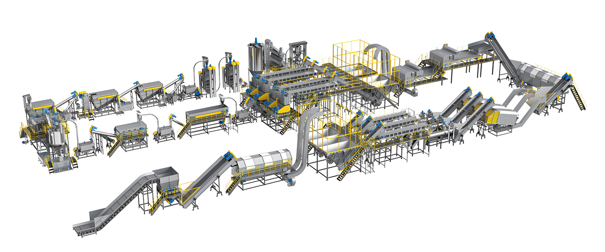
The PTW series is Polyretec’s soft plastic crushing and washing line, engineered for post-consumer and post-industrial PP and PE film, woven sacks, agricultural film and food grade flexible packaging. The series designation follows nominal line throughput: PTW1000 denotes the 1000 kg per hour configuration, which is the reference machine deployed in a fully automated PP and PE plastic film washing installation in Taiwan. Line capacity across the series spans 500 to 1500 kg per hour, and a one-step pelletizing option is available where the customer wants pellets rather than washed flake as the end product.
The shredding front end of a PTW line is built on the Austrian-engineered principles described earlier: a low-speed high-torque rotor, a hydraulic pusher ram with load-following control, a V-profile cutting chamber with no horizontal ledges, square indexable blades with four usable edges, a hinged screen cradle for single-operator access, and adjustable rotor-to-screen clearance to hold particle size stable as blades wear. Food grade configurations add stainless steel contact surfaces, radiused internal transitions, food-grade H1 lubricant throughout, and a documented cleaning and changeover protocol.
PTW series shredding module specifications
| Parameter | PTW500 | PTW1000 | PTW1500 |
|---|---|---|---|
| Nominal line throughput | 500 kg/h | 1000 kg/h | 1500 kg/h |
| Cutting chamber size, width by depth | 800 × 600 mm | 1000 × 800 mm | 1200 × 900 mm |
| Rotor diameter | 320 mm | 400 mm | 450 mm |
| Rotor speed | 90–110 rpm | 80–100 rpm | 70–95 rpm |
| Rotating blades, indexable, four edges each | 30 pieces | 44 pieces | 56 pieces |
| Counter knives | 2 pieces | 2 pieces | 2 pieces |
| Blade material and hardness | Cold work tool steel of the D2 / SKD-11 type, heat treated to 58–62 HRC; powder metallurgy grade optional for abrasive feed | ||
| Screen aperture range | 30–80 mm | 30–80 mm | 40–80 mm |
| Standard screen for food grade film | 60 mm | 60 mm | 60–80 mm |
| Rotor-to-screen clearance, adjustable | 0.3–1.0 mm | 0.3–1.0 mm | 0.3–1.0 mm |
| Main drive motor | 45 kW | 75 kW | 110 kW |
| Drive architecture | High-torque planetary gear direct drive standard; hydraulic drive available for heavily contaminated feed | ||
| Hydraulic pusher ram | Yes, load-following | Yes, load-following | Yes, load-following |
| Hydraulic power unit | 5.5 kW | 7.5 kW | 11 kW |
| Infeed opening, length by width | 1000 × 900 mm | 1400 × 1100 mm | 1600 × 1200 mm |
| Feed conveyor | Cleatless or cleated food grade belt, speed 5–15 m/min, with overband magnet and inductive metal detector | ||
| Overload protection | Automatic reverse and retry on torque threshold, fault stop after defined retry count | ||
| Anti-wrap provision | Anti-wrap discs with fixed scrapers at both rotor ends, external protected shaft seals, inspection covers | ||
| Contact surfaces, food grade configuration | Stainless steel 304 standard, 316L optional where chloride or caustic wash chemistry is present | ||
| Lubrication | Food-grade H1 lubricant on all points with a credible path to product | ||
| Noise at operator position | Below 85 dB(A) with standard enclosure and correct installation | ||
| Control system | PLC with touch screen HMI, motor load logging, screen and blade set identification, recipe management, remote monitoring option | ||
Values in this table are typical configuration figures for planning purposes. Final specification, including chamber dimensions, blade count and motor rating, is confirmed against the customer’s material sample, target particle size and duty cycle during project engineering.
What a complete PTW line contains after the shredder
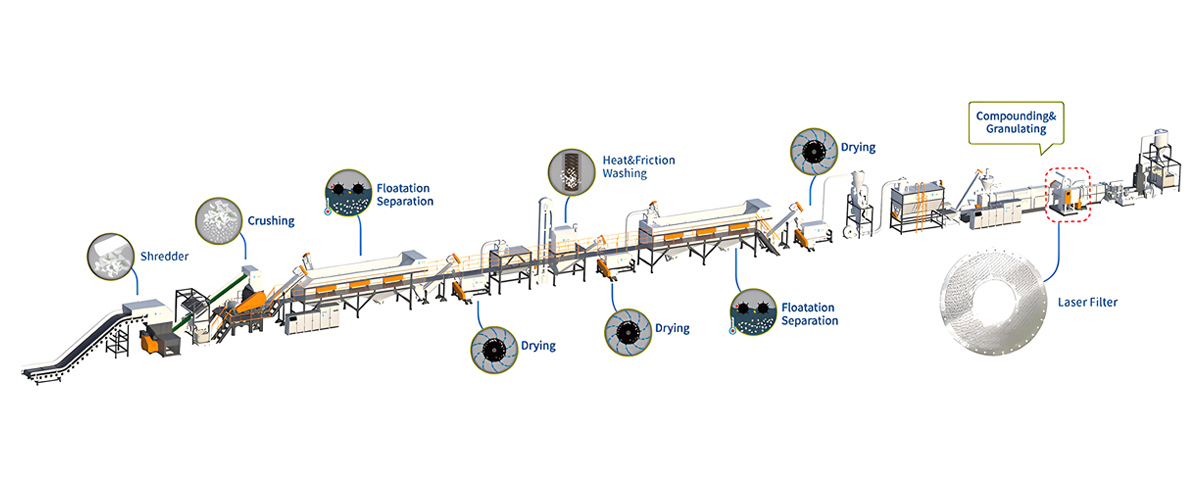
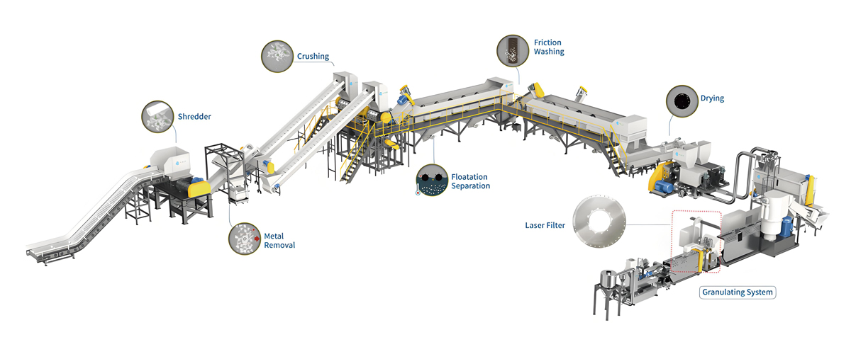
The shredding module is one station in a continuous line. A typical PTW1000 configuration for food grade PP and PE film runs as follows: bale feed conveyor with de-wiring station, single-shaft shredder with 60 mm screen, screw conveyor to a pre-wash tank for gross soil and stone removal, high-speed friction washer, float-sink separation tank with paddle transport for polymer and density separation, a second friction washing stage with hot wash where fat and label adhesive removal demands it, squeezing dewatering machine, thermal drying with a hot air pipe dryer and cyclone, and a storage silo. Where the customer wants pellets, the line continues into a pelletizing stage rather than terminating at washed flake.
The reason to present the shredder in the context of the whole line is that the shredder’s settings only make sense in relation to what follows. A 60 mm screen is correct for this line because the friction washer downstream is designed for film fragments in that size range. Change the downstream equipment and the correct screen changes with it.
Polyretec Food Grade PET Bottle Washing Line Shredding Module
The Polyretec food grade PET bottle washing line is the second major product line relevant to this discussion, covering 500 kg per hour to 6000 kg per hour and configurable for different output flake grades — from general-purpose flake through fiber grade to the high-purity grade required where recycled PET is intended for food contact applications under an approved decontamination process.
The size reduction stage in a PET bottle line is architecturally different from the PTW film line. Bottles are thin-walled, rigid and easy to cut, so a heavy-duty granulator configured as a wet crusher is the primary machine. Process water is injected directly into the cutting chamber, which suppresses dust completely, removes frictional heat, begins dissolving sugar residue at the moment of cutting, and starts carrying loosened label material and grit away from the flake. On lines handling large containers, drums or heavily compacted bales, a single-shaft shredder is installed upstream of the wet crusher as a pre-shredding stage.
Wet crushing module specifications
| Parameter | 500 kg/h | 1000 kg/h | 2000 kg/h | 3000 kg/h | 6000 kg/h |
|---|---|---|---|---|---|
| Nominal line throughput | 500 kg/h | 1000 kg/h | 2000 kg/h | 3000 kg/h | 6000 kg/h |
| Cutting chamber size, width by depth | 600 × 500 mm | 800 × 600 mm | 1000 × 800 mm | 1200 × 900 mm | 1500 × 1000 mm |
| Rotor diameter | 350 mm | 400 mm | 500 mm | 600 mm | 700 mm |
| Rotor speed | 420–480 rpm | 400–460 rpm | 380–440 rpm | 350–420 rpm | 320–400 rpm |
| Rotating fly knives | 9 pieces, 3 rows of 3 | 15 pieces, 3 rows of 5 | 20 pieces, 4 rows of 5 | 24 pieces, 4 rows of 6 | 32 pieces, 4 rows of 8 |
| Fixed bed knives | 2 pieces | 2 pieces | 2 pieces | 2 pieces | 3 pieces |
| Knife material and hardness | Cold work tool steel of the D2 / SKD-11 type, 58–62 HRC, reground in complete sets | ||||
| Screen aperture range | 12–20 mm | 12–20 mm | 14–20 mm | 16–25 mm | 16–25 mm |
| Standard screen, food grade flake | 14 mm | 14 mm | 16 mm | 16 mm | 18 mm |
| Typical flake size produced | 8–14 mm characteristic dimension depending on screen and knife condition | ||||
| Rotor-to-bed-knife clearance | 0.3–0.6 mm, checked at multiple positions across the rotor width | ||||
| Main drive motor | 37 kW | 55 kW | 90 kW | 132 kW | 200 kW |
| Water injection into the cutting chamber | Standard; suppresses dust and heat, initiates washing at the moment of cutting | ||||
| Infeed opening, length by width | 700 × 500 mm | 900 × 600 mm | 1100 × 800 mm | 1300 × 900 mm | 1600 × 1000 mm |
| Upstream pre-shredder | Single-shaft shredder recommended where the feed contains drums, large containers or hard-compacted bales | ||||
| Metal protection | Overband magnet and inductive metal detector on the feed conveyor; eddy current separator where aluminum neck rings are present | ||||
| Contact surfaces, food grade configuration | Stainless steel 304 standard, 316L where wash chemistry or water quality demands it | ||||
| Screen access | Hinged cradle with quick-release clamps, single-operator access for cleaning and changeover | ||||
| Lubrication | Food-grade H1 lubricant on all points with a credible path to product | ||||
| Control system | PLC with touch screen HMI, motor load and throughput logging, batch identification, remote monitoring option | ||||
As with the PTW table, these are typical configuration values used for project planning. Final specification is confirmed against the customer’s bale specification, target flake grade and washing chemistry during project engineering.
Why the PET line uses a granulator where the film line uses a shredder
The contrast between Table 12 and Table 13 is instructive, because it illustrates that machine class follows material rather than preference. PET bottles are thin-walled and brittle enough to fracture cleanly at high rotor speed, they arrive at high bulk density in bales, and the downstream washing chemistry works best on 8 to 14 mm flake. That combination points squarely to a wet granulator.
Film is elastic, low in bulk density, prone to wrapping and unnecessary to reduce below roughly 60 mm for friction washing. That combination points squarely to a low-speed single-shaft shredder with ram feeding. Running film through a high-speed granulator produces heat, fines and wrapped shafts; running baled bottles through a slow shredder alone produces flake too coarse for the washing chemistry. Both machines are correct — for their own material.
Application Industries and Real Waste Stream Formats
Specification decisions become concrete once the actual waste format is named. The following are the food grade and adjacent streams Polyretec equipment most frequently processes, described in the physical form in which they arrive at the plant gate rather than as abstract polymer categories.
Food grade rigid packaging
PP and PE returnable crates and trays arrive as whole units, sometimes nested, from beverage distribution, bakery logistics, fish and produce handling. They carry organic residue, adhesive label remnants, occasional metal fasteners and, in fish and meat logistics, significant protein and fat soil. Format: rigid, hollow, 400 to 600 mm in plan, wall thickness 2 to 5 mm. Processing route: single-shaft shredder with 40 to 60 mm screen, metal separation, wet granulation to 10 to 15 mm, hot friction washing, float separation, dewatering, drying.
HDPE dairy and beverage bottles arrive baled or loose, with closures, ring collars and sleeve labels. Format: thin-wall rigid, high bulk volume when loose. Processing route: pre-shredding where baled hard, wet granulation to 10 to 14 mm, friction washing, float separation to remove PP closures, dewatering, drying.
PET beverage bottles arrive baled and sorted by color, with caps, ring collars and labels. Format: thin-wall rigid, 15 to 30 grams per unit. Processing route: bale opening, manual sorting, metal separation, wet crushing to 8 to 14 mm flake, pre-wash, hot caustic wash where required for adhesive and residual polyvinyl chloride removal, friction washing, float separation, rinsing, dewatering, drying, optional air classification and optical sorting.
Food grade drums, jerry cans and intermediate bulk container liners arrive as large hollow rigid items, occasionally with residual liquid content. Format: 20 to 220 liters, wall thickness 2 to 6 mm. Processing route: manual inspection and draining, twin-shaft pre-shredding or a large single-shaft shredder with 60 to 80 mm screen, metal separation, granulation, intensive hot washing.
Food grade flexible packaging and film
Bread bags, produce bags and food overwrap film arrive loose or lightly baled, with print, and with bread crumb, flour and produce soil. Format: LDPE and LLDPE, 15 to 60 micrometers, low bulk density. Processing route: baling or densification to raise bulk density, single-shaft shredder with 60 to 80 mm screen, pre-wash, friction washing, float separation, mechanical dewatering, thermal drying, then either flake packing or a pelletizing stage.
Shrink film and pallet stretch film from food distribution arrive as loose rolls and used wraps, generally with lower soil load than consumer film. Format: LLDPE, 12 to 35 micrometers, prone to wrapping. Processing route: single-shaft shredder with 60 to 80 mm screen and full anti-wrap provision, friction washing, dewatering, drying, pelletizing.
Woven PP sacks and big bags from food ingredient handling arrive folded or baled, carrying flour, sugar, starch or grain residue and often paper liners. Format: woven tape fabric, 60 to 200 grams per square meter. Processing route: single-shaft shredder with 60 mm screen and reinforced anti-wrap discs, dry pre-cleaning to remove bulk powder residue, friction washing, float separation to remove paper, dewatering, drying.
Adjacent industrial and agricultural streams
Daily chemical packaging — HDPE detergent and personal care bottles, PP closures and caps — is a high-volume adjacent stream that shares equipment with food grade rigid lines but must be strictly segregated from food grade production, with a full documented changeover between campaigns. Format: rigid, pigmented, with residual surfactant content that changes wash water chemistry.
Agricultural film — greenhouse film, mulch film, silage wrap — arrives heavily contaminated with soil, stones, plant matter and moisture, often at soil loads exceeding the plastic mass. Format: LDPE, 20 to 200 micrometers, extremely abrasive feed. Processing route: dry shaking and pre-cleaning, single-shaft shredder with powder metallurgy blades and 80 mm screen, multi-stage wet pre-washing with grit removal, friction washing, float separation, dewatering, drying, pelletizing with melt filtration.
Industrial film and technical packaging — protective films, liner films, industrial shrink hoods — is a cleaner stream that behaves well and is often used as the commissioning material when a new line is started, before the plant moves to its dirtier design case.
| Waste stream | Physical format at intake | Primary machine | Screen aperture | Second stage | Key risk to manage |
|---|---|---|---|---|---|
| Food grade PP and PE crates and trays | Whole rigid units, 400–600 mm, 2–5 mm wall | Single-shaft shredder | 40–60 mm | Wet granulator to 10–15 mm | Metal fasteners, protein and fat residue |
| Food grade PET bottle bales | Baled thin-wall bottles with caps and labels | Wet granulator, pre-shredder if hard-baled | 14–18 mm | Not required | Aluminum neck rings, adhesive labels, sugar residue |
| HDPE dairy and beverage bottles | Baled or loose, closures attached | Wet granulator, pre-shredder if baled | 10–14 mm | Not required | Milk protein soil, PP closure separation |
| Food grade drums and jerry cans | 20–220 liter hollow rigid, 2–6 mm wall | Twin-shaft pre-shredder or large single-shaft | 60–80 mm | Granulator to 12–15 mm | Residual liquid content, metal handles and fittings |
| Food grade LDPE bags and overwrap film | Loose or lightly baled, 15–60 micrometers | Single-shaft shredder | 60–80 mm | Not required | Low bulk density, shaft wrapping, print ink load |
| Food distribution shrink and stretch film | Used wraps and part rolls, 12–35 micrometers | Single-shaft shredder | 60–80 mm | Not required | Severe wrapping risk; anti-wrap discs mandatory |
| Woven PP ingredient sacks | Folded or baled woven fabric with liners | Single-shaft shredder | 60 mm | Optional granulation before pelletizing | Fiber wrapping, paper liner separation, powder residue |
| Daily chemical rigid packaging | Baled HDPE bottles with PP closures | Single-shaft shredder then granulator | 40 mm then 12 mm | Wet granulator | Strict segregation from food grade campaigns |
| Agricultural film with soil | Rolled or bundled, heavily soiled, wet | Single-shaft shredder, abrasion-resistant tooling | 80 mm | Not required | Extreme abrasive wear, grit removal, high moisture |
| Industrial protective and liner film | Baled clean film, low soil load | Single-shaft shredder | 60–80 mm | Not required | Static charge, low bulk density |
Requirement to Model Selection Guide
The following table condenses the preceding analysis into a direct recommendation path: describe the waste, the volume and the intended downstream process, and read across to the Polyretec configuration and screen aperture that fits. It is a starting point for a technical conversation rather than a substitute for one, because the material sample almost always reveals something the description omitted.
| Waste type and intake format | Typical intake size | Target throughput | Downstream process | Recommended Polyretec configuration | Screen aperture |
|---|---|---|---|---|---|
| Food grade LDPE bags and food overwrap film, baled | Bales up to 1200 × 800 mm | 500 kg/h | Friction washing then flake packing | PTW500 crushing and washing line, single-shaft shredder front end | 60 mm |
| Food grade PP and PE film, mixed print, baled | Bales up to 1400 × 1100 mm | 1000 kg/h | Friction washing, float separation, drying | PTW1000 crushing and washing line, fully automated configuration | 60 mm |
| Food grade film with one-step pelletizing required | Bales up to 1400 × 1100 mm | 1000 kg/h | Washing then direct pelletizing | PTW1000 with one-step pelletizing option | 60 mm |
| Mixed PP and PE film and woven sacks, high volume | Bales up to 1600 × 1200 mm | 1500 kg/h | Washing, drying, pelletizing | PTW1500 with reinforced anti-wrap discs | 60–80 mm |
| Agricultural film with soil and grit | Bundles, wet and heavy | 1000–1500 kg/h | Multi-stage pre-washing, grit removal, pelletizing | PTW1000 or PTW1500 with powder metallurgy blades and extra pre-wash stages | 80 mm |
| Food grade PET bottles, sorted and baled, small plant | Standard mill-size bales | 500 kg/h | Hot wash, float separation, drying, flake sale | Food grade PET bottle washing line, 500 kg/h wet crushing module | 14 mm |
| Food grade PET bottles, sorted and baled | Standard mill-size bales | 1000–2000 kg/h | Hot caustic wash, friction washing, drying, fiber or sheet grade flake | Food grade PET bottle washing line, 1000 or 2000 kg/h configuration | 14–16 mm |
| Food grade PET bottles, high-purity flake target | Standard mill-size bales, tightly specified | 3000 kg/h | Hot wash, intensive friction washing, air classification, optical sorting | Food grade PET bottle washing line, 3000 kg/h configuration with pre-shredder | 16 mm |
| Food grade PET, large industrial plant | Continuous baled supply | 6000 kg/h | Full food grade flake production with decontamination downstream | Food grade PET bottle washing line, 6000 kg/h configuration with single-shaft pre-shredder | 16–18 mm |
| Food grade PP and PE rigid crates and trays | Whole units, 400–600 mm | 1000–1500 kg/h | Granulation, hot washing, float separation, drying | Hard PP and PE crushing and washing line with single-shaft shredder front end plus wet granulator | 40–60 mm then 12 mm |
| Food grade drums, jerry cans and large containers | 20–220 liter units | 500–1000 kg/h | Granulation, intensive hot washing | Hard PP and PE line with large-opening single-shaft shredder and wet granulator | 80 mm then 12–15 mm |
| Washed flake to be converted into pellets on site | Washed and dried flake | Matched to washing line output | Melt filtration and pelletizing | Polyretec pelletizing line, or matched twin-screw pelletizing systems supplied by Wanplas for direct integration with Polyretec washing lines | Not applicable |
Two notes on using this table. First, where two stages appear in the screen column, the first figure is the shredder screen and the second is the granulator screen. Second, where a customer’s target throughput falls between two configurations, the correct answer is usually the larger machine with a coarser screen rather than the smaller machine pushed to its limit, because the larger machine runs at a lower load factor, wears its tools more slowly and leaves capacity for the inevitable growth in feed contamination over the life of the plant.
Integration with Washing, Drying and Pelletizing
A shredder specified in isolation will disappoint even when it performs exactly to specification, because the value of size reduction is realized entirely downstream. The handoff parameters between stages are therefore worth writing into the project specification alongside the machine data.
The full process sequence
A complete food grade recycling line runs: intake and bale storage, bale opening and de-wiring, manual sorting, metal separation, shredding, optional granulation, pre-washing, friction washing, float-sink separation, hot washing where residue demands it, rinsing, mechanical dewatering, thermal drying, air classification and quality screening, storage, and finally either flake packing or pelletizing with melt filtration.
Each interface between two stages has an acceptance parameter, and the discipline of writing those parameters down converts a collection of machines into a designed process.
| Interface | Key handoff parameter | Typical target | Consequence of missing the target |
|---|---|---|---|
| Sorting to shredder | Foreign material content | Below 2 percent by mass for food grade streams | Blade damage, metal contamination, unplanned stoppages |
| Shredder to granulator | Particle size, upper bound | Below the granulator feed limit, typically 60–80 mm | Bridging at the granulator throat, throughput collapse |
| Shredder or granulator to pre-wash | Particle size distribution width | Narrow; characteristic dimension within roughly plus or minus 40 percent | Uneven residence time, inconsistent cleaning |
| Pre-wash to friction washer | Gross soil and grit removed | Sand and stone essentially absent | Accelerated abrasive wear on friction washer screens and rotors |
| Friction washer to float tank | Surface soil removed, flake wetted | Organic load substantially reduced | Surface soil alters apparent density and defeats float separation |
| Float tank to dewatering | Polymer separation achieved | Target polymer purity per grade specification | Contaminant polymer carries through to the pellet |
| Mechanical dewatering to thermal drying | Residual moisture after the centrifuge | 3–8 percent, material and flake size dependent | Drying energy rises steeply; dryer becomes the line bottleneck |
| Thermal drying to flake storage | Residual moisture at storage | Below 1 percent for general flake sale | Microbial growth risk, caking, weight disputes |
| Flake to pelletizing, polyolefins | Moisture at the extruder feed throat | Typically below 1 percent, with degassing in the barrel | Voids in the strand, unstable melt pressure, foaming at the die |
| Flake to pelletizing, PET | Moisture at the extruder feed throat | Typically below 0.02 percent after crystallizing and drying | Hydrolytic degradation and severe loss of intrinsic viscosity |
| Pelletizing to product | Melt filtration fineness and pellet size consistency | Per end application specification | Gels, black specks and screen changer blockage in the customer’s process |
Why the shredder sets the dewatering result
The moisture line in Table 16 deserves emphasis because it links directly back to the screen aperture decision made at the shredder. Mechanical dewatering removes surface water, and surface water is proportional to surface area. Finer flake carries more surface area per kilogram and therefore exits a centrifugal dryer at the wetter end of the 3 to 8 percent range, while coarser flake exits at the drier end.
Because thermal drying is one of the most energy-intensive operations in the whole line, an unnecessarily fine screen at the shredder shows up as a permanent increase in dryer energy consumption for the life of the plant. The correct approach is to select the coarsest particle size that the washing chemistry and the downstream converter will accept, not the finest the machine can produce.
Downstream pelletizing
Where the customer’s business model calls for pellets rather than washed flake, the washing line terminates at a storage silo and a pelletizing stage takes over: feeding, melting and homogenizing in an extruder, melt filtration to remove residual solid contaminants, degassing to remove moisture and volatiles, and cutting into pellets by strand, water ring or underwater systems. Polyretec supplies pelletizing lines including a new generation configuration engineered for thin-walled LDPE film as well as thick-walled PE and PP regrind, built for the demanding reality of post-consumer waste. For customers whose formulation requires compounding capability alongside recycling — adding stabilizers, impact modifiers, fillers or color during the recycling pass — Wanplas supplies matched twin-screw pelletizing systems that integrate directly with Polyretec washing lines, so a single project team delivers the complete route from bale to finished pellet.
Cleaning, Changeover and Traceability SOP
A hygienically designed shredder delivers food grade capability only when it is operated under a written procedure. The following is the structure of a workable cleaning and changeover standard operating procedure for a shredding station, expressed as a sequence that a plant can adapt to its own quality system.
Changeover categories
Not every changeover requires the same level of cleaning, and treating them all identically is the fastest way to guarantee that none of them is done properly. Three categories cover most plants.
A same-grade batch change — one lot of food grade PP crates followed by another lot of the same material from a different supplier — requires the machine to be run empty, the chamber and screen to be visually inspected, and the batch record to be closed and a new one opened. Time required is minutes.
A grade change within food grade — for example, natural HDPE dairy bottles followed by colored food grade PP — requires the machine to be run empty, the chamber, hopper, ram face and screen to be physically cleared, and a documented visual inspection at defined points. Color carryover is the risk being managed. Time required is typically under an hour.
A category change into or out of food grade — for example, daily chemical packaging followed by a food grade campaign — requires the full cleaning procedure with washdown, inspection at every defined point, and a sign-off. This is the changeover that the plant’s food safety argument rests on, and it should never be compressed.
| Step | Action | Verification | Record |
|---|---|---|---|
| 1 | Stop feeding, run the machine empty until the discharge conveyor is clear and motor load returns to no-load | Motor load reading at no-load, visual check of discharge | Run-out time and closing batch identifier |
| 2 | Apply energy isolation: main disconnect locked, hydraulic circuit isolated and residual pressure relieved, ram parked in the service position | Zero-energy verification by the assigned technician | Lockout and tagout register entry with technician name |
| 3 | Open the hopper access and swing out the screen cradle | Guard interlock released only at verified rotor standstill | Not required |
| 4 | Remove residual material from the chamber floor, ram face, rotor pockets, counter knife seats and the anti-wrap zone at both rotor ends | Visual inspection under adequate lighting at each defined point | Estimated residual mass recovered |
| 5 | Remove and clean the screen; inspect for blinded holes, cracks and deformation | Held to the light; blocked hole count assessed | Screen identification number and condition |
| 6 | Washdown of all contact surfaces where the changeover category requires it, using the plant’s approved detergent and water temperature | Visual cleanliness at each defined inspection point; surface swab where the quality system requires it | Detergent, concentration, temperature, contact time |
| 7 | Rinse and drain; confirm no standing water in the chamber or the ram guide channel | Visual check, drain point clear | Not required |
| 8 | Inspect blades and counter knives; index or replace as the schedule requires; check and reset the rotor-to-counter-knife and rotor-to-screen clearances | Feeler gauge readings at multiple positions across the rotor width | Blade set identifier, index event, measured clearances |
| 9 | Refit the screen for the next product, close the cradle, close the hopper access, verify interlocks | Interlock function test before energy restoration | Screen aperture installed for the new batch |
| 10 | Restore energy, run empty for a defined period, then discharge and quarantine the first defined quantity of the new material as a flush | Visual check of the flush material for carryover | Flush quantity and disposition |
| 11 | Open the new batch record and start production | Supervisor sign-off on the completed changeover checklist | New batch identifier, screen, blade set, operator, start time |
Cleaning validation
Validation converts the procedure above from a claim into evidence. The method is to select the worst-case soil the plant actually handles — usually a high-fat, high-protein residue — deliberately process it, execute the cleaning procedure exactly as written, and then assess the defined inspection points against the acceptance criterion. Repeating this successfully on three separate occasions is the conventional threshold for demonstrating reproducibility. The validation report should record the soil used, the procedure version, the inspection points, the results, the personnel involved and the conclusion. Revalidation is triggered by any change to the procedure, the detergent, the machine configuration or the material categories processed.
Traceability records at the shredding station
The batch record generated at the shredder is the anchor for the whole traceability chain. At minimum it should capture: batch identifier and the incoming consignment identifiers that feed it; start and stop times; the screen aperture and screen identification number installed; the blade set identifier and the index or replacement state; the operator and shift; the motor load and throughput profile logged by the control system; every fault, reversal and unplanned stop with its cause; the preceding batch and the changeover category executed between them; and the disposition of any quarantined flush material.
Modern control systems on Polyretec equipment log the machine-generated portion of this automatically, and the operator-entered portion is a short checklist. Plants that treat this record as a compliance burden tend to fill it in retrospectively and inaccurately; plants that treat it as a process control tool discover that the motor load and throughput logs are the earliest available warning of blade wear, screen blinding and feed quality drift.
Maintenance Schedule and Wear Part Management
A shredder in continuous food grade service needs a maintenance regime that is scheduled rather than reactive. The economic argument is straightforward: a planned blade index during a scheduled stop costs an hour of production, while an unplanned blade failure during a run costs a shift, a screen, sometimes a blade holder, and a batch of off-specification material.
| Interval | Task | Acceptance criterion |
|---|---|---|
| Every shift | Visual inspection of the cutting chamber, hopper and screen through the access opening | No accumulation on internal surfaces, no visible screen blinding |
| Every shift | Inspect both rotor ends and the anti-wrap zone | No film or fiber winding at the shaft ends |
| Every shift | Check motor load and throughput against the batch baseline | Within the expected band for the material and screen in use |
| Every shift | Check hydraulic system for leaks and confirm oil level and temperature | No leaks, level within the sight glass band, temperature within range |
| Every shift | Verify emergency stop devices and guard interlocks function | All devices operate and are logged as tested |
| Daily | Clean the chamber, hopper and screen at end of production | Visual cleanliness at all defined inspection points |
| Daily | Empty and inspect the dust extraction collection point | No dust accumulation on horizontal surfaces around the machine |
| Weekly | Inspect blade edges and record wear condition against the reference photographs | Edge radius within the acceptable band; no chipping |
| Weekly | Check rotor-to-counter-knife clearance with a feeler gauge at multiple positions | Within the specified band, uniform across the rotor width |
| Weekly | Grease all lubrication points with food-grade H1 lubricant per the lubrication chart | Grease relief clear, correct grease type verified by color |
| Weekly | Clean the anti-wrap discs and inspect the scraper clearance | Scraper clearance within specification |
| Weekly | Inspect the feed conveyor belt, magnet and metal detector function with a test piece | Detector triggers reliably on the standard test piece |
| Monthly | Index blades to a fresh edge, or earlier if wear indicators require it | All blades on the rotor at the same edge condition |
| Monthly | Check and reset rotor-to-screen clearance | Within the 0.3–1.0 mm specification band |
| Monthly | Inspect shaft seals and bearing condition, including temperature and vibration trend | No seal leakage, bearing temperature and vibration within trend limits |
| Monthly | Inspect the hydraulic ram face, guide rails and wipers | Ram face profile intact, no material trapped behind the wipers |
| Monthly | Verify the control system logs are complete and archived | No gaps in the batch record series |
| Quarterly | Full internal inspection with the screen cradle and hopper section removed | No cracking at weld transitions, no wear breakthrough on liner plates |
| Quarterly | Hydraulic oil sample and filter change | Oil condition within specification, filter differential pressure normal |
| Quarterly | Gearbox oil level, condition and breather check | Level correct, no water ingress, breather clear |
| Quarterly | Inspect and re-torque all blade holder and counter knife fasteners | All fasteners at specified torque |
| Quarterly | Review blade life, energy per ton and throughput trends against the baseline | Trends stable or explained; corrective actions raised where not |
| Annually | Gearbox oil change, full electrical inspection, safety system validation | Complete safety function test report signed off |
| Annually | Review and revalidate the cleaning procedure | Validation report current and covering all material categories processed |
Wear part inventory
The spare parts a plant should hold on site are determined by lead time and by the cost of downtime, not by the cost of the part.
| Wear part | Indicative service life | Recommended stock | Replacement or scrap indicator |
|---|---|---|---|
| Rotating blade inserts | 300–1500 hours per edge, four edges per insert | One complete set plus ten percent spares | Chip deeper than the regrind allowance, any visible crack, thickness below the holder clamping minimum |
| Counter knives | Similar to rotating blades, often slightly longer | One complete set | Edge rounding beyond regrind allowance, seating face deformation |
| Blade holder fasteners | Replace at every second index cycle | Three complete sets | Any thread damage or elongation; never reuse a stretched fastener |
| Screens | 2000–6000 hours depending on abrasion | One of each aperture in regular use | Hole enlargement beyond tolerance, cracking at the ligaments, permanent deformation |
| Anti-wrap discs and scrapers | 4000–8000 hours | One set | Scraper clearance no longer adjustable to specification |
| Rotor shaft seals | 6000–12000 hours | Two sets | Any leakage, or grease emerging on the chamber side |
| Chamber liner plates | 8000–20000 hours | One set for high-wear zones | Wear through to the base plate or loss of the radiused transition profile |
| Hydraulic seals and hoses | Hoses on a scheduled replacement interval regardless of condition | One hose set, one seal kit | Any weeping, abrasion through the outer cover, or exceeded service interval |
| Hydraulic filter elements | Per the quarterly schedule or on differential pressure | Two sets | Differential pressure indicator triggered |
| Ram wipers and guide rail seals | 3000–6000 hours | One set | Material found behind the wiper during inspection |
Reading the machine as an instrument
The most useful maintenance practice costs nothing: treat the motor load and throughput logs as a condition monitoring instrument. Three patterns carry clear diagnostic meaning.
Throughput falling at constant motor load indicates that discharge is restricted — a blinding screen, most often, or a discharge conveyor that is backing up. Check the screen first.
Motor load rising at constant throughput indicates that cutting has become less efficient — dull blades, incorrect counter knife clearance, or material being dragged and heated rather than sheared. Check clearances, then index the blades.
Both falling together, with an increasingly ragged load trace indicates a feeding problem — ram pressure set too low, low bulk density feed, bridging in the hopper, or an upstream conveyor delivering intermittently. Check the feed before touching the machine.
A plant that trains its operators to read these three patterns will catch most developing problems days before they become stoppages, and will avoid the common and expensive error of changing blades to solve a feeding problem.
Relative Cost of Ownership
Total cost of ownership for a shredding station has four components: capital, energy, tooling and labor. Their relative weight over a ten-year life differs sharply by machine class and by material, and the ranking is frequently the opposite of what the purchase decision assumed.
| Configuration | Capital cost | Energy cost per ton | Tooling cost per ton | Labor and maintenance | Overall ten-year position |
|---|---|---|---|---|---|
| Belt-driven high-speed granulator alone, dry, on film | Low | Very High | Very High | High | Very High; the classic false economy on film streams |
| Belt-driven single-shaft shredder, gravity fed | Low to Medium | High | High | Medium to High | High; throughput shortfall dominates the economics |
| Austrian-engineered single-shaft shredder, planetary direct drive, hydraulic ram | Medium to High | Medium | Medium | Low to Medium | Low to Medium; the reference configuration for film and rigid streams |
| Same machine in food grade configuration with stainless contact surfaces | High | Medium | Medium | Medium, cleaning labor added | Medium, offset by substantially higher output value |
| Hydraulic drive single-shaft shredder | High | Medium to High | Low to Medium | Medium | Medium; justified where feed contamination is severe and unpredictable |
| Twin-shaft pre-shredder plus single-shaft shredder in series | Very High | Medium | Low to Medium | Medium | Medium; the only viable route for very bulky rigid feed |
| Single-shaft shredder plus wet granulator in series | High | Medium | Medium | Medium | Low to Medium; the standard food grade rigid packaging route |
| Wet granulator alone on baled PET bottles | Medium | Low | Medium | Low to Medium | Low; the correct and efficient route for this specific material |
The pattern to notice is that the lowest capital option is almost never the lowest total cost, and that the gap widens with operating hours. On a two-shift operation running four thousand hours a year, energy and tooling together dominate the ten-year cost, and both are governed by the design decisions discussed in this article: drive efficiency, feeding control, screen aperture, blade material and clearance discipline.
The second pattern is that the food grade configuration premium is a capital cost, largely one-time, while the value uplift from selling into food contact markets is recurring on every ton. For a plant with a credible route to that market, the payback arithmetic is rarely close.
Service and Support from Polyretec
Equipment specification is only half of a recycling project. The other half is what happens after the container is unloaded, and it is the half that determines whether the line reaches its rated output in six weeks or six months.
Before shipment
Every Polyretec line is assembled and tested at the factory before shipment. Where the customer supplies a representative material sample, the shredding module is trialed on that material and the resulting particle size, throughput and motor load profile are documented, so the acceptance test at site is a repeat of a known result rather than a first attempt. Customers are welcome to attend the factory test in person — Polyretec, in line with the Wanplas open factory policy, welcomes customer visits to see the machines being built and tested rather than only in photographs. Where travel is impractical, the test is recorded and reviewed with the customer remotely before the line is packed.
Installation and commissioning
Polyretec engineers attend site for installation supervision and commissioning. The commissioning sequence covers mechanical alignment, hydraulic circuit setup and ram pressure calibration, control system configuration including load-following parameters, safety system verification with every interlock and emergency stop tested, blade and counter knife clearance setting, and a staged production ramp on the customer’s own material. With more than one hundred completed projects and service coverage extending across more than fifty countries, the commissioning team arrives with experience of the specific waste stream rather than only of the machine.
Training
Operator and maintenance training is delivered at commissioning and covers the areas where plants most often lose performance: reading motor load and throughput as process indicators, indexing blades and setting clearances correctly, screen changing and cleaning, executing the changeover procedure, safe jam clearing without entering the chamber, and the lockout and tagout procedure. Training is documented, and the training record forms part of the plant’s food safety file.
Spare parts and warranty
Polyretec applies the Wanplas group service policy: USD 500 of free spare parts every year, and free replacement of parts damaged within the warranty period. In practice this covers the routine consumable items that a plant needs and frequently forgets to order, and it keeps a communication channel open between the plant and the factory during the first years of operation. Recommended wear part stocking is set out in Table 19, and Polyretec supplies blade sets, counter knives, screens, seals and hydraulic components for the full service life of the equipment.
Remote support and ongoing service
Where the control system includes the remote monitoring option, Polyretec engineers can review machine data directly and support fault diagnosis without a site visit, which is often the difference between an hour of downtime and a week of waiting for a technician’s flight. Polyretec maintains a team of more than twenty-four engineers available for customer assistance, and supports customers with process optimization after commissioning — adjusting screen apertures, revising blade schedules and retuning ram control as the plant’s actual feed evolves away from the material it was originally specified for. That evolution is universal, and a supplier relationship that continues after the warranty expires is what keeps a line producing to specification in year five.
Frequently Asked Questions
What does Austrian technology actually mean in a plastic shredder?
It refers to a design school rather than a place of manufacture: a low-speed high-torque rotor running at roughly 60 to 120 rpm, a planetary gear direct drive or hydraulic drive, a hydraulic pusher ram with load-following control, a V-shaped cutting chamber with counter knives producing a true shear cut, square indexable blades with four usable edges, and adjustable rotor-to-screen clearance. Polyretec applies these Austrian-engineered principles and manufactures the resulting machine in China. When comparing offers, evaluate each of these parameters against the quoted specification rather than relying on origin claims, because the parameters are verifiable and the claims are not.
Can a shredder make recycled plastic food grade on its own?
No. Food grade status attaches to a recycling process as a whole, assessed against defined input specifications and operating conditions — through EFSA opinions in the European Union within the framework that includes EU 10/2011, and through the FDA no-objection letter route in the United States. A shredder supports that argument by not introducing contamination, by being cleanable to a validated standard, and by producing a controlled particle size that lets the washing and decontamination stages perform as designed. It cannot carry an approval of its own, and any supplier suggesting otherwise is describing something that does not exist.
Which screen aperture should I choose for food grade film?
For food grade PP and PE film feeding a friction washing line, 60 mm is the standard choice and 80 mm is appropriate for very bulky or heavily soiled feed such as agricultural film. Finer screens do not improve washing performance on film, because a friction washer handles 60 mm film fragments perfectly well, but they raise specific energy consumption steeply, reduce throughput and generate fines that complicate dewatering. Select the coarsest aperture your downstream process will accept, then verify it on a material trial rather than assuming.
How long do shredder blades last on food grade waste?
A realistic planning range is 300 to 1500 operating hours per cutting edge, and because square indexable inserts carry four edges, a complete set typically delivers roughly four times that before it leaves the machine. Clean food grade PP crates and sorted PET bottle bales sit at the upper end; agricultural film carrying soil and grit sits at the lower end. Regrinding recovers a further one to two sets of edges from most inserts. The dominant variable is feed contamination, not machine quality, which is why metal separation and manual sorting upstream pay for themselves in tooling cost alone.
Do I need a single-shaft shredder, a twin-shaft shredder or a heavy-duty granulator?
Match the machine class to the material. A single-shaft shredder is the primary choice for film, bags, woven sacks, crates and baled material, producing 15 to 80 mm output set by screen aperture. A twin-shaft shredder is a pre-shredder for very bulky rigid items such as intermediate bulk containers, pallets and thick-wall drums, producing coarse 50 to 200 mm output without particle size control. A heavy-duty granulator is the second-stage machine producing 6 to 20 mm flake, and it is the primary machine for baled PET bottles when configured as a wet crusher. Many food grade lines use two classes in series.
How do I stop film from wrapping around the rotor shaft?
Wrapping is controlled geometrically, not operationally. Specify anti-wrap discs with fixed scrapers at both rotor ends, minimize the gap between the rotor end face and the chamber wall with a replaceable wear ring, locate the shaft seal outside the chamber behind the anti-wrap disc with an outward grease relief path, and fit inspection covers that allow a shift-change visual check without dismantling. Then add the procedural half: remove all strapping at the bale de-wiring station, since steel strapping is the single most damaging item that enters a plastic shredder and is entirely preventable.
What residual moisture should I expect after dewatering?
Mechanical dewatering in a centrifugal machine typically leaves 3 to 8 percent surface moisture, with the exact figure depending on flake size and geometry — finer flake carries more surface area per kilogram and therefore exits wetter. Thermal drying then takes the material below 1 percent for general flake sale. Pelletizing imposes stricter requirements: polyolefins are typically fed below 1 percent with barrel degassing, while PET requires crystallizing and drying to roughly 0.02 percent to avoid hydrolytic loss of intrinsic viscosity during extrusion.
How is the shredder kept below 85 dB(A)?
A low-speed shear-cutting shredder with a planetary direct drive is inherently much quieter than a high-speed granulator. Holding the operator position below 85 dB(A) requires attention to four contributors: helical blade layout for progressive rather than pulsed cutting; vibration isolation to limit structure-borne noise; a remote or enclosed hydraulic power pack where a hydraulic drive is used; and treatment of the discharge and conveying system, which is frequently the loudest element once the machine itself has been addressed. Where a granulator is present, an acoustic enclosure with cleanable internal surfaces is normally added.
What is required for a food grade changeover between material campaigns?
Classify the changeover first. A same-grade batch change needs a run-out, a visual inspection and a batch record closure. A grade change within food grade adds physical clearing of the chamber, hopper, ram face and screen with documented inspection. A category change into or out of food grade requires the full procedure: run-out, energy isolation with lockout and tagout, chamber and screen clearing, washdown with the approved detergent, inspection at every defined point, blade and clearance check, a flush quantity that is quarantined, and supervisor sign-off. The full procedure should be validated against a worst-case soil and revalidated whenever the procedure, detergent or material categories change.
Which Polyretec configuration fits a 1000 kg per hour food grade film project?
The PTW1000 crushing and washing line is the direct match, with a single-shaft shredder front end at 1000 mm by 800 mm cutting chamber, 400 mm rotor, 44 indexable blades, a 75 kW planetary direct drive, a hydraulic pusher ram and a 60 mm screen. It is the same configuration deployed in a fully automated PP and PE film washing installation in Taiwan. A one-step pelletizing option is available where pellets rather than washed flake are the intended product, and where compounding capability is required during the recycling pass, Wanplas supplies matched twin-screw pelletizing systems that integrate directly with Polyretec washing lines.
Conclusion
A plastic shredder for food grade plastic waste is defined by three things at once: what it cuts, how cleanly it can be cleaned, and what it hands to the process downstream. The Austrian-engineered design route addresses all three simultaneously. Low rotor speed and shear cutting keep the polymer cool and the organic residue loose rather than baked on. Planetary direct drive and hydraulic ram feeding hold the machine at a high, stable load factor, which is where the energy savings and the consistent particle size both come from. Square indexable blades and adjustable clearances keep tooling cost and output quality under control across the life of a blade set. And the hygienic detailing — radiused internal transitions, stainless contact surfaces, hinged screen access, food-grade H1 lubricant, documented cleaning and batch traceability — is what makes the difference between flake that can enter a food contact application and flake that cannot.
None of these features is exotic, and none is expensive relative to what it protects. What they require is a specification written before the purchase order rather than discovered afterward: a named material with a stated bulk density and moisture content, a target particle size justified by the downstream process rather than by instinct, a machine class matched to the waste format, a screen aperture chosen as the coarsest the process will accept, a metal protection strategy with all three layers present, and a throughput guarantee qualified against all of it. The tables in this article are intended to be used in exactly that way — as a checklist against which any offer, from any supplier, can be evaluated line by line.
Polyretec, a Wanplas factory, has built plastic recycling equipment since 2010 and formalized the brand in 2017, with over one hundred completed projects, service coverage across more than fifty countries, a team of more than twenty-four engineers, and a decade of continuous commitment to customers who bought a line and then had to make it work every day. The PTW series crushing and washing lines from 500 to 1500 kg per hour, and the food grade PET bottle washing lines from 500 to 6000 kg per hour, are built on the Austrian-engineered shredding principles described here and configured project by project against the customer’s actual waste stream. Factory testing before shipment, on-site installation and commissioning, documented operator and maintenance training, USD 500 of free spare parts every year, remote diagnostic support and an open factory policy for customer visits all come as part of the Wanplas brand commitment.
If you are specifying a shredding stage for a food grade recycling project, send us the material: a description of the waste format at intake, an estimate of bulk density and moisture, your target throughput, the downstream process you intend to feed, and the output grade your customers require. Our engineers will trial your sample, propose a configuration with screen aperture and blade specification stated explicitly, and document the particle size and throughput achieved so that the acceptance test at your site is a repeat of a result you have already seen. You are also welcome to visit the factory and watch your line being built and tested before it ships.