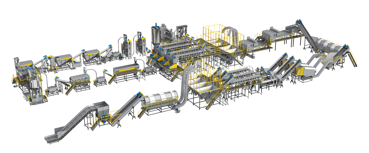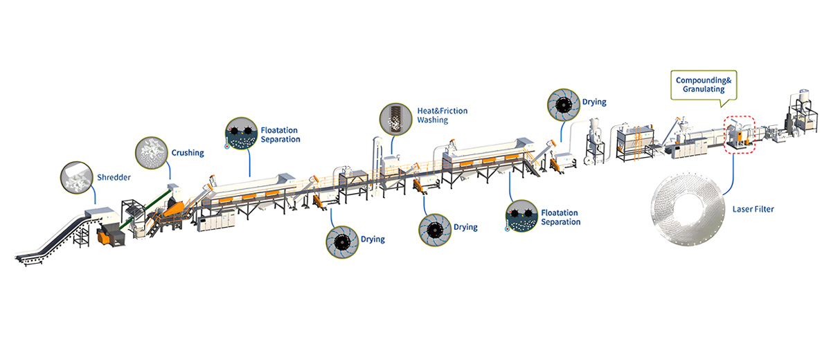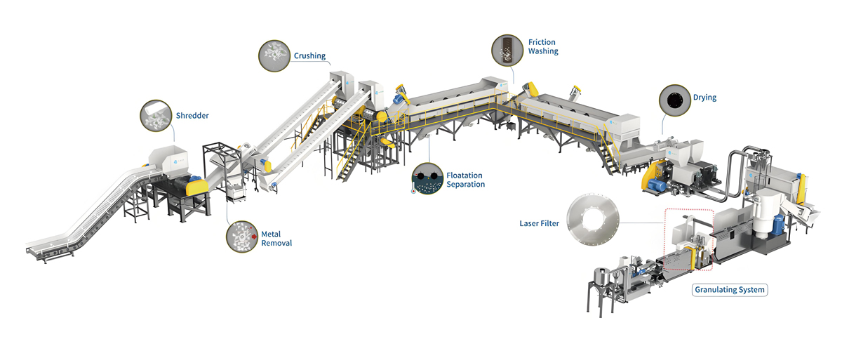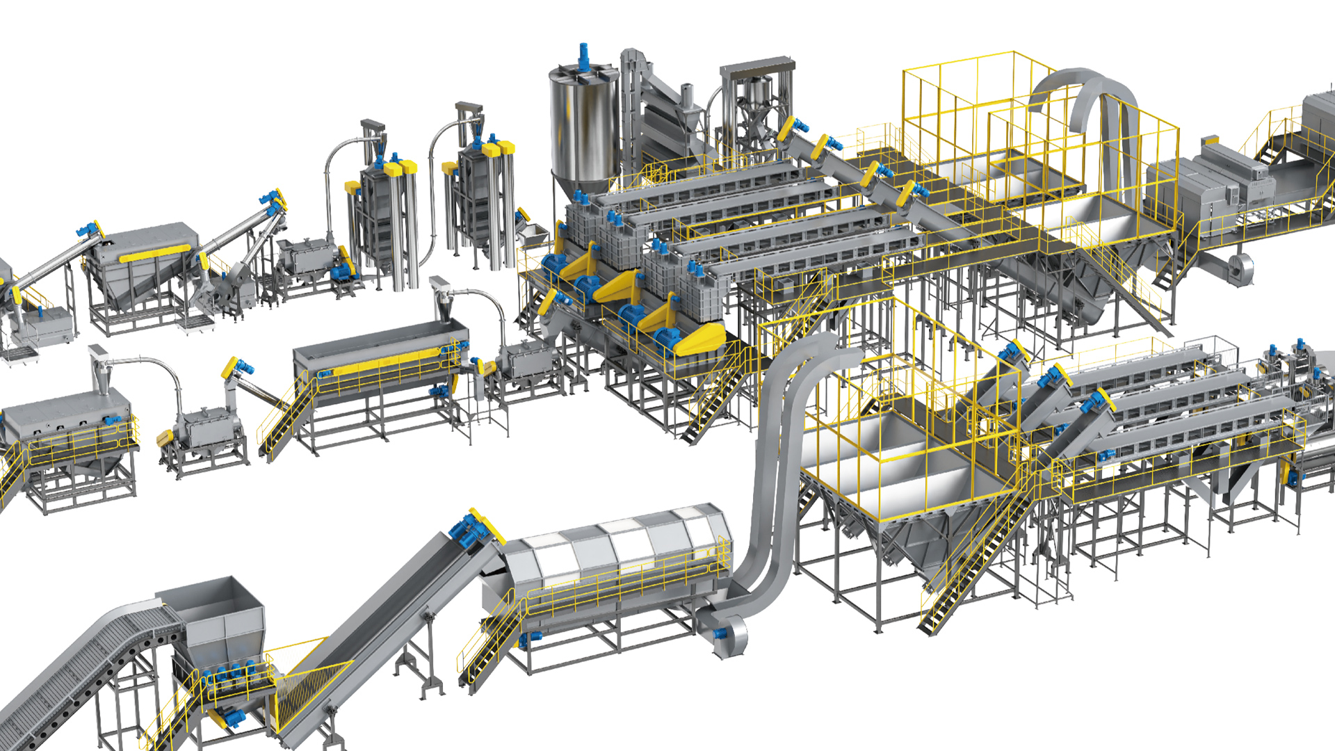

Printed and sticky low-density polyethylene film is the single most demanding feedstock in flexible plastics recycling, and the pelletizing line that handles it must be designed around contamination removal rather than around throughput alone. A line built for clean post-industrial trim will choke on printed shopping bags, adhesive-laminated label liner and mud-loaded agricultural film within days of startup. Choosing the best LDPE film pelletizing line for printed and sticky film waste therefore means choosing a coordinated chain of wet size reduction, friction washing, hot caustic washing, mechanical dewatering, force feeding, vented extrusion and melt filtration, where each stage is dimensioned against the specific contamination load the plant actually receives.
Polyretec, a Wanplas factory, has been building plastic recycling equipment since 2010 and established the Polyretec brand in 2017, accumulating more than 100 completed projects, service coverage across more than 50 countries and a team of more than 24 engineers. The factory’s soft PP and PE crushing and washing lines run from 500 to 1500 kilograms per hour, and its New Generation Pelletizing Line is engineered specifically for thin-walled LDPE film and thick-walled PE and PP regrind from post-consumer sources. Delivered installations include an LDPE film recycling and pelletizing system for printed bags and films, and a washing line for LDPE film carrying pressure-sensitive stickers built around a heavy-duty shredder and a beater machine. This guide draws on that engineering baseline to explain, stage by stage, what a printed and sticky LDPE line has to do and how to specify it.
The article works through feedstock characterization, the full process chain, wet crushing geometry, hot wash chemistry, the dewatering cascade, force feeding, screw and venting design, the single-stage versus two-stage decision, melt filtration, pelletizing head selection, real Polyretec line specifications, a requirement-to-configuration selection guide, a troubleshooting matrix, energy and yield benchmarks, and the end markets that absorb the finished pellet. Every parameter given is a project-planning value that gets confirmed against a real material sample during engineering, because printed film varies more between suppliers than almost any other recycling feedstock.
Why Printed and Sticky LDPE Film Is the Hardest Film Stream to Pelletize
Printed and sticky LDPE film combines four problems that most other recycling feedstocks present only one or two of at a time: extremely low bulk density, high surface-to-mass ratio, chemically bonded surface contamination, and a strong tendency to wrap and knot around any rotating shaft. Each of these degrades a different part of the line, and a line that solves only one of them will still fail.
Bulk density is the first constraint. Loose LDPE film sits at roughly 0.02 to 0.05 tonnes per cubic meter, which is between one twentieth and one thirtieth of the bulk density of virgin pellet. A gravity hopper feeding a standard extruder throat cannot deliver enough mass per unit time to keep a screw fed, so output collapses to a fraction of nameplate. Every design decision downstream of the washing line, from feeder geometry to screw flight depth, exists to compensate for that number.
The second constraint is surface area. A 20 to 40 micrometer film has an enormous surface-to-mass ratio, which means that contamination sitting on the surface represents a much larger percentage of total mass than the same contamination on a thick-walled part. A soil layer that would be trivial on a 3 millimeter crate wall becomes several percent by weight on thin film. It also means that water clings tenaciously: the same surface area that holds soil holds moisture, and mechanical dewatering has to fight it at every stage.
The third constraint is the contamination chemistry itself. Print layers on LDPE film are typically 2 to 8 micrometers thick and consist of pigment, binder resin, and in many cases a nitrocellulose or polyurethane vehicle. Pigment particles are inorganic or organic solids that survive melt temperatures intact and report directly to the ash content of the finished pellet. Adhesive residue is worse: pressure-sensitive adhesives based on acrylic or styrene block copolymer chemistry soften at 40 to 60 degrees Celsius, become tacky inside compaction equipment, and carry through into the melt as gel-forming domains that will not disperse into the polyethylene matrix.
The fourth constraint is mechanical wrapping. Film strips wrap around shafts, rotors, screw conveyors and dewatering augers. Every rotating component in the wet section of a film line needs either an anti-wrap geometry, a scraper, or a maintenance access design that lets an operator clear a wrap in minutes rather than hours. Lines designed for rigid flake and then sold into film service are the most common source of chronic downtime in the industry.
Together these constraints define the machine. A printed and sticky LDPE film pelletizing line is not a washing line with an extruder bolted on the end; it is an integrated system where the wet section is dimensioned to deliver a specific flake condition to the extruder and the extruder is dimensioned to accept exactly that condition.
Feedstock Characterization: Ink Layers, Adhesives, Soil and Bulk Density
Correct line specification starts with an honest characterization of the incoming material, because the difference between clean post-industrial printed film and post-consumer agricultural film is a factor of five in wash energy and a factor of two in capital configuration. The three variables that matter most are total contamination percentage, contamination type, and incoming moisture.
Total contamination is measured by taking a representative sample of at least 20 kilograms across several bales, washing it to completion in a laboratory, drying it, and weighing the recovered polymer. The difference is the contamination load. Values below 1 percent indicate post-industrial trim. Values of 2 to 5 percent indicate typical post-consumer packaging film. Values of 8 to 20 percent, sometimes higher, indicate agricultural film carrying soil, sand, plant residue and irrigation grit.
Contamination type determines the removal mechanism. Surface soil comes off with mechanical agitation and warm water. Ink requires either chemical attack on the binder or mechanical abrasion of the print layer, and in practice needs both. Adhesive requires temperature plus surfactant to reduce tack, followed by mechanical shear to detach it. Paper labels require prolonged soaking to break fiber bonds. Metallized layers and aluminum foil laminate cannot be washed off at all and must be removed by sorting before the line or accepted as a permanent quality penalty.
Incoming moisture matters because it changes the heat balance of the hot wash tank and the load on the dewatering equipment. Baled film received in a dry climate typically arrives at 5 to 8 percent moisture. Agricultural film pulled directly from a field can arrive at 15 percent or higher, with much of that water bound up in adhering soil. A line sized on dry-bale assumptions will run short of thermal capacity in the hot wash tank the first time a wet load arrives.
Table 1 — LDPE film feedstock types, contamination level and recommended process route
| Feedstock type | Typical contamination by weight | Dominant contaminant | Recommended process route | Extrusion architecture |
|---|---|---|---|---|
| Post-industrial LDPE trim, unprinted | Below 0.5 percent | Dust, process oil traces | Dry crushing, optional dust removal, direct pelletizing | Single-stage, single vent |
| Post-industrial printed film edge trim | 0.5 to 1.5 percent | Surface ink, solvent residue | Wet crushing, friction washing, short warm wash, squeezer | Single-stage with vacuum vent |
| Post-consumer LDPE shopping bags, printed | 2 to 5 percent | Ink, food residue, paper labels | Wet crushing, friction washing, hot caustic wash 80 to 90 degrees Celsius, rinse, centrifuge, squeezer | Single-stage with vacuum vent, or two-stage |
| Stretch and shrink wrap, lightly printed | 1 to 3 percent | Tape residue, dust, pallet grit | Wet crushing, friction washing, warm wash, brief float separation, squeezer | Single-stage with vacuum vent |
| Label liner and adhesive-laminated film | 4 to 10 percent | Pressure-sensitive adhesive, silicone release, paper fiber | Wet crushing, extended hot wash with surfactant, double friction washing, double rinse, squeezer | Two-stage mandatory |
| Agricultural mulch and greenhouse film | 8 to 20 percent | Soil, sand, grit, plant matter | Pre-wash and grit removal, heavy-duty wet crushing, multi-stage friction washing, hot wash, rinse, centrifuge, squeezer | Two-stage with coarse first-pass filtration |
| Mixed post-consumer LDPE and LLDPE, heavily printed | 5 to 12 percent | Mixed ink systems, adhesive, organic residue | Full wet chain with extended hot wash and reinforced friction washing | Two-stage with automatic filtration |
| Multi-layer laminate with barrier ply | Variable, structural | Non-PE barrier layer, reverse-printed ink | Wash for surface soil only; barrier layer is not removable | Two-stage with fine filtration, accept color and gel penalty |
Table 2 — Contamination chemistry and the mechanism that actually removes it
| Contaminant | Typical layer or load | Removal mechanism | Process stage that does the work | Realistic removal efficiency |
|---|---|---|---|---|
| Solvent-based surface print | 2 to 8 micrometer ink film | Caustic hydrolysis of binder plus mechanical abrasion | Hot wash tank plus friction washer | 70 to 90 percent |
| Water-based surface print | 3 to 6 micrometer ink film | Surfactant wetting plus mechanical abrasion | Friction washer with warm water | 75 to 92 percent |
| Reverse-printed laminate ink | Encapsulated between plies | None available by washing | Not removable; color homogenization only | Effectively zero |
| Acrylic pressure-sensitive adhesive | 15 to 30 grams per square meter | Thermal softening plus surfactant plus shear detachment | Hot wash 85 to 90 degrees Celsius plus second friction washer | 60 to 85 percent |
| Hot-melt adhesive, block copolymer | Discrete beads and stripes | Softening then mechanical stripping; partial melt dispersion | Hot wash plus melt filtration | 50 to 75 percent removed, remainder filtered |
| Paper labels and fiber | 1 to 4 percent by weight | Fiber swelling, disintegration, flotation removal | Soak tank, friction washer, water overflow | 90 to 98 percent |
| Field soil, sand, grit | 3 to 15 percent by weight | Mechanical agitation plus sedimentation | Pre-wash tank, grit trap, friction washer | 92 to 99 percent |
| Food and organic residue | 0.5 to 3 percent | Caustic saponification plus warm water dissolution | Hot wash tank | 90 to 98 percent |
| Metal fragments, staples, wire | Sporadic | Magnetic and eddy-current separation | Infeed magnet plus melt filtration backstop | Above 99 percent if magnet is fitted |
| Sand and mineral fines below 200 micrometers | Variable | Hydrocyclone and settling; melt filtration backstop | Rinse loop and melt filter | 85 to 95 percent |
Table 3 — Bulk density and handling behavior by film format
| Material format | Bulk density, tonnes per cubic meter | Wrapping tendency | Conveying method | Design consequence |
|---|---|---|---|---|
| Loose baled film, as received | 0.25 to 0.45 in bale | Not applicable | Bale conveyor with de-wiring station | Bale breaker required before crushing |
| Loose film after bale breaking | 0.02 to 0.05 | Very high | Wide belt conveyor, low speed | Oversized conveyor cross-section |
| Wet crushed film flake, 40 to 60 millimeter | 0.06 to 0.11 | High | Screw conveyor with anti-wrap shaft | Anti-wrap geometry mandatory |
| Washed film flake after centrifuge | 0.10 to 0.16 | Moderate | Screw or pneumatic conveying | Moisture 3 to 8 percent at this point |
| Squeezed and pre-plasticized crumb | 0.28 to 0.42 | Low | Short chute directly into extruder throat | Feeds a screw reliably without a crammer |
| Agglomerated film crumb | 0.30 to 0.45 | Low | Screw or pneumatic conveying | Alternative route where a squeezer is not used |
| Finished pellet, 3 by 3 millimeter | 0.50 to 0.58 | None | Pneumatic conveying to silo | Standard handling |
The Complete LDPE Film Pelletizing Line Process Chain
A complete LDPE film pelletizing line for printed and sticky waste consists of thirteen functional stations, and the specification of each one depends on the contamination profile established during feedstock characterization. Understanding the chain as a sequence of state changes, rather than as a list of machines, is what allows an engineer to judge whether a proposed configuration is sufficient.
The material enters as a compressed bale at 0.25 to 0.45 tonnes per cubic meter, is opened into loose film at 0.02 to 0.05, is size-reduced and wetted into flake at 0.06 to 0.11, is progressively cleaned and moisture-reduced through the wash chain, is mechanically compacted to 0.28 to 0.42, is melted and filtered, and finally leaves as pellet at 0.50 to 0.58. Contamination is removed in parallel with these density changes, and the line is only as good as its weakest removal stage.
Table 4 — Station-by-station function map of the LDPE film pelletizing line
| Station | Primary function | Material state on exit | Key specification driver |
|---|---|---|---|
| 1. Bale conveyor and de-wiring | Meter bales into the line, remove baling wire | Intact bale on conveyor | Bale dimensions and weight |
| 2. Bale breaker or heavy-duty shredder | Open the bale, tear film into handleable pieces | Loose film, 200 to 400 millimeter pieces | Bale density and presence of foreign objects |
| 3. Metal separation | Remove ferrous and non-ferrous fragments | Metal-free film | Source of waste stream |
| 4. Pre-wash and grit removal | Strip gross soil, sand and stones before crushing | Film with grit load reduced | Soil load; mandatory for agricultural film |
| 5. Wet crusher | Size-reduce to flake under water injection | Flake 40 to 60 millimeter, saturated | Blade gap 0.5 to 1 millimeter, screen aperture |
| 6. Friction washer, first pass | High-speed mechanical scrubbing of ink and soil | Flake with surface contamination loosened | Rotor speed 700 to 1000 rpm |
| 7. Hot wash tank | Chemical attack on ink binder, adhesive and organics | Flake with ink and adhesive largely detached | 80 to 90 degrees Celsius, 1 to 2 percent caustic, 10 to 20 minutes |
| 8. Friction washer, second pass | Shear off chemically loosened contamination | Clean flake, chemical carry-over present | Rotor speed, residence, water flow |
| 9. Float separation and rinse | Remove sinking contaminants, neutralize chemistry | Rinsed flake, near-neutral pH | Handled briefly; density difference between PE and contaminants |
| 10. Centrifugal dewatering | Bulk mechanical water removal | Flake at 3 to 8 percent moisture | Rotor speed, screen slot width |
| 11. Mechanical squeezer | Compaction dewatering plus frictional pre-heating | Crumb at 2 to 5 percent moisture, warm | Compression ratio, drainage slot design |
| 12. Extrusion with force feeder and vacuum vent | Melt, degas, homogenize | Filtered, degassed melt | L/D 30 to 36, vent vacuum minus 0.06 to minus 0.09 MPa |
| 13. Filtration, pelletizing, drying, storage | Remove solids, cut and cool pellet, dry and convey | Dry pellet, 3 by 3 millimeter | Screen mesh 80 to 150, cutting head type |
Two stations on this list are routinely under-specified by buyers comparing quotations on price. The first is station 4, pre-wash and grit removal, which is often deleted from a quotation to reduce cost and then becomes the reason blade life on the wet crusher drops from 800 hours to 200 hours. The second is station 11, the mechanical squeezer, which is sometimes replaced by a longer thermal dryer; that substitution works on clean film but fails on printed film because the squeezer contributes bulk density and pre-heating as well as dewatering.
Float separation appears at station 9, and on printed film lines it plays a supporting role rather than a starring one. LDPE floats, and most of what needs removing at that point already sank in the earlier tanks or was carried off by overflow. The rinse function, restoring pH and flushing residual chemistry off the flake surface, is the more important job at this station on a printed film line.
Bale Breaking, Infeed Conveying and Wet Crushing
Size reduction on printed and sticky film has one purpose that overrides all others: create a flake geometry that the wash chain can clean and the feeder can convey, without generating fines that will be lost as yield. Everything about blade gap, screen aperture and rotor speed follows from that.
Bale breaking comes first. Baled film arrives compressed to 0.25 to 0.45 tonnes per cubic meter and bound with steel or plastic wire. Feeding an intact bale into a crusher is the fastest way to destroy a rotor. A bale breaker or a low-speed high-torque shredder opens the bale into 200 to 400 millimeter pieces, and a de-wiring station removes the binding. On sticker-contaminated film, a heavy-duty shredder is preferred over a simple bale breaker because it also delaminates stacked layers that adhesive has bonded together.
Wet crushing is where the working flake geometry is established. Water is injected directly into the cutting chamber at a rate of roughly 1.5 to 3 cubic meters per hour per tonne of throughput. The water performs four jobs simultaneously: it suppresses dust completely, it carries away soil and grit before that grit can abrade the blades a second time, it cools the blades and prevents localized melting of the polyethylene, and it begins the wetting process that the friction washer will finish.
Blade gap is the parameter that separates a good film crusher from a poor one. For film, the gap between rotating and fixed blades must be held at 0.5 to 1 millimeter. A wider gap lets film fold into the gap instead of being cut, producing long ragged strips that wrap on every downstream shaft. A tighter gap causes blade-to-blade contact under thermal expansion and destroys the cutting edges. Because film gives almost no cutting resistance, the operator gets no audible or load-based warning that the gap has drifted; it must be checked on a fixed schedule, typically every 200 to 300 operating hours.
Screen aperture controls flake size. For LDPE film, a 40 to 60 millimeter screen is standard, with 60 to 80 millimeters used on heavily soiled agricultural film where fines generation must be minimized and downstream washing capacity is generous. Screens finer than 40 millimeters generate excessive fines, and fines in film recycling are pure yield loss because they pass through dewatering screens and leave with the water.
Table 5 — Wet crusher configuration for printed and sticky LDPE film
| Parameter | Printed packaging film | Adhesive-laminated film | Agricultural film with soil | Notes |
|---|---|---|---|---|
| Rotor speed | 420 to 500 rpm | 380 to 460 rpm | 380 to 450 rpm | Lower speed reduces fines and heat |
| Blade gap | 0.5 to 0.8 millimeter | 0.5 to 0.8 millimeter | 0.6 to 1.0 millimeter | Check every 200 to 300 hours |
| Screen aperture | 40 to 60 millimeter | 50 to 60 millimeter | 60 to 80 millimeter | Finer screens raise fines loss |
| Water injection rate | 1.5 to 2.5 cubic meters per hour per tonne | 2.0 to 3.0 | 2.5 to 3.5 | Higher for abrasive loads |
| Blade material | Tool steel, hardened | Tool steel, hardened | Powder metallurgy grade | Grit demands wear-resistant grades |
| Blade service life, indicative | 600 to 900 hours between indexes | 500 to 800 hours | 200 to 400 hours | Strongly dependent on grit removal upstream |
| Rotor design | Open rotor, staggered blades | Open rotor, staggered blades | Open rotor, reinforced hub | Staggering reduces peak torque |
| Chamber drainage | Continuous, screened sump | Continuous, screened sump | Continuous with grit trap | Grit trap prevents recirculation of abrasives |
| Anti-wrap provision | Shaft sleeves and scrapers | Shaft sleeves, scrapers, heated seal area | Shaft sleeves and scrapers | Adhesive builds up at seals |
| Typical specific energy | 0.05 to 0.09 kilowatt hours per kilogram | 0.06 to 0.10 | 0.07 to 0.12 | Rises sharply with dull blades |
One practical note on adhesive-contaminated film: pressure-sensitive adhesive accumulates preferentially at the shaft seals and in the corners of the cutting chamber, where flow velocity is lowest. A crusher intended for sticker-laden film should have a chamber with radiused internal transitions and no horizontal ledges, and a documented weekly cleaning procedure. Adhesive build-up that is allowed to carbonize becomes the source of black specks in the finished pellet three weeks later, long after the cause has been forgotten.
Friction Washing and Hot Wash Chemistry for Ink and Adhesive Removal
The friction washer and the hot wash tank together do 80 to 90 percent of the contamination removal on a printed film line, and they work as a pair: the tank chemically weakens the bond between contaminant and polymer, and the friction washer supplies the mechanical energy that actually detaches it. Specifying one without the other produces a line that either wastes chemicals or wastes mechanical energy.
Friction washing mechanics
A friction washer is a vertical or inclined drum containing a high-speed rotor fitted with paddles, running inside a perforated screen. Flake enters at the bottom, is thrown outward against the screen by the rotor, and travels upward while being scrubbed against the screen and against other flakes. Water is injected counter-current, so the dirtiest water leaves at the bottom and the cleanest contact happens at the top.
Rotor speed for film service runs at 700 to 1000 revolutions per minute. Below 700 rpm there is not enough centrifugal force to press flake against the screen hard enough for abrasion. Above 1000 rpm on thin film, the dominant effect becomes fines generation rather than cleaning, and yield suffers. The correct speed within that band depends on flake size and contamination type: larger flake and tougher ink push toward the upper end, thin lightly printed film toward the lower end.
Residence time in a single friction washer pass is short, typically 20 to 60 seconds. That is why printed film lines almost always use two friction washers, one before the hot wash tank and one after. The first pass removes loose soil and reduces the load on the chemistry; the second pass removes the contamination that the chemistry has loosened. Running one friction washer twice as long is not equivalent, because the chemical step in between is what makes the second pass effective.
Hot wash chemistry
The hot wash tank is a heated, agitated vessel with a controlled residence time, and for printed and sticky LDPE film the working window is well established. Temperature runs at 80 to 90 degrees Celsius. Caustic soda concentration runs at 1 to 2 percent by weight. A non-ionic surfactant package is dosed at 0.1 to 0.4 percent. Residence time is 10 to 20 minutes.
Each of those four variables does something specific. Temperature reduces the viscosity of adhesive residue and accelerates every chemical reaction in the tank; below 75 degrees Celsius, adhesive removal falls off sharply. Caustic hydrolyzes ester linkages in ink binders and saponifies fatty organic residues, converting them into water-soluble soaps. Surfactant lowers interfacial tension so that water can wet the hydrophobic polyethylene surface and penetrate under detached contamination. Residence time gives the chemistry the contact it needs; below 8 minutes, ink removal on solvent-based print systems becomes unreliable.
There is an upper limit as well. Temperatures above 95 degrees Celsius and caustic above 3 percent begin to attack the polyethylene surface itself, generating carbonyl groups that reduce the oxidative stability of the finished pellet and cause color drift toward yellow during extrusion. Long residence at high caustic also consumes chemical needlessly, and every gram of caustic put into the tank has to be neutralized and disposed of later.
Table 6 — Hot wash operating window by contamination type
| Contamination profile | Temperature | Caustic concentration | Surfactant dosing | Residence time | Friction washer passes |
|---|---|---|---|---|---|
| Light surface print, low soil | 70 to 78 degrees Celsius | 0.5 to 1.0 percent | 0.1 to 0.2 percent | 8 to 12 minutes | 1 to 2 |
| Heavy solvent-based print | 82 to 90 degrees Celsius | 1.5 to 2.0 percent | 0.2 to 0.3 percent | 15 to 20 minutes | 2 |
| Water-based print with food residue | 80 to 88 degrees Celsius | 1.0 to 1.5 percent | 0.2 to 0.4 percent | 12 to 18 minutes | 2 |
| Pressure-sensitive adhesive, label liner | 85 to 90 degrees Celsius | 1.5 to 2.0 percent | 0.3 to 0.4 percent | 18 to 20 minutes | 2, second pass reinforced |
| Hot-melt adhesive beads | 85 to 90 degrees Celsius | 1.0 to 1.5 percent | 0.3 to 0.4 percent | 15 to 20 minutes | 2 plus melt filtration backstop |
| Agricultural film, soil dominant | 75 to 85 degrees Celsius | 0.8 to 1.5 percent | 0.1 to 0.2 percent | 10 to 15 minutes | 2 to 3 |
| Mixed post-consumer, worst case | 85 to 90 degrees Celsius | 1.5 to 2.0 percent | 0.3 to 0.4 percent | 18 to 20 minutes | 3 |
Chemical consumption is a real operating cost and should be modeled during project engineering. Caustic make-up is driven by two losses: neutralization by acidic soil components, and carry-over on the flake surface into the rinse. A well-designed tank with a dewatering screw at the outlet and a caustic recovery rinse returns most of the carry-over to the tank, and cuts caustic consumption to roughly one third of what an open-transfer design uses. On the cost scale used in this guide, chemical consumption for a printed film line is Medium, and for a label liner line it is High.
Practical notes on adhesive removal
Adhesive removal has a characteristic that catches new operators: it works well or it works badly, with little middle ground. The reason is that pressure-sensitive adhesive detaches as a cohesive film once the interfacial bond is broken, but if the interfacial bond is not broken it stays completely attached. Temperature is the switch. A tank running at 78 degrees Celsius will show poor adhesive removal, and the same tank at 86 degrees Celsius will show good removal, with the transition happening over a narrow band. This is why hot wash tanks on adhesive-heavy lines need reliable temperature control and adequate heating capacity for the worst-case wet feed, not just for the average.
The second practical note is that detached adhesive must be removed from the water loop immediately, or it re-deposits on clean flake. A skimmer at the tank surface plus a fine screen in the recirculation loop handles this. Lines without adhesive removal from the water loop show a puzzling pattern where wash efficiency deteriorates over a shift and recovers after a water change; that is re-deposition, not chemistry failure.
Rinsing, Density Correction and the Dewatering Cascade
Everything between the last friction washer and the extruder throat exists to solve one problem: get water out of a material with an enormous surface area, without losing yield and without spending excessive thermal energy. The answer is a mechanical cascade, where each stage removes the water that the previous stage could not.
Rinsing and pH restoration
Flake leaving the second friction washer carries caustic-laden water on its surface. That water has to be replaced with clean water before dewatering, for three reasons. Residual caustic corrodes the stainless steel of downstream equipment over time. Caustic carried into the extruder promotes color drift and can catalyze degradation. And caustic carried into the pellet cooling water contaminates the pellet water loop.
A counter-current rinse in two stages brings surface pH from around 11 to 12 down to 7.5 to 8.5 with modest fresh water consumption. Counter-current means the cleanest water contacts the cleanest flake, and the water cascades backward toward the dirtier stages before leaving the system. This is a plumbing decision, not an equipment decision, and it costs nothing at the design stage while saving substantial water for the life of the plant.
Density separation happens at this point on many film lines. Because LDPE has a density of roughly 0.918 to 0.925 grams per cubic centimeter and water is 1.0, polyethylene floats while soil, grit, metal fragments, paper pulp and denser polymers sink. On a printed and sticky film line this stage is a useful backstop rather than the main event, since the majority of the removable contamination has already gone. It is worth having, and it is not worth over-engineering on this stream.
Centrifugal dewatering
A vertical or horizontal centrifugal dryer takes flake at 25 to 40 percent surface moisture and brings it to 3 to 8 percent. It works by throwing flake outward against a perforated screen with a high-speed rotor, typically 700 to 1200 revolutions per minute depending on machine size. Water passes through the screen slots; flake travels upward along the screen and discharges at the top.
The critical specification is screen slot width. Slots of 0.6 to 1.2 millimeters are typical for film flake. Wider slots pass more water but also lose more fines. Narrower slots retain fines but blind more quickly with fiber and film shards. On printed film with paper label residue, slot blinding is a real maintenance item, and the machine needs an accessible screen for daily inspection.
Mechanical squeezing
The mechanical squeezer, sometimes called a squeezer dryer or a plastificator, is the stage that makes a film pelletizing line work. It is a screw press with a heated or self-heating barrel and a restricted discharge. As the screw compresses wet flake against the restriction, water is forced out through drainage slots in the barrel wall, and the frictional work heats the material to 90 to 130 degrees Celsius. The output is a warm, partly softened crumb at 2 to 5 percent moisture and 0.28 to 0.42 tonnes per cubic meter bulk density.
The squeezer delivers three benefits at once. It removes water mechanically, which costs far less energy than evaporating the same water thermally. It raises bulk density by a factor of three to four, which is what allows the extruder to be fed reliably. And it pre-heats the material, which reduces the melting load on the extruder and shortens the residence time needed for full plasticizing. On a printed film line, deleting the squeezer to save capital is a false economy that shows up immediately as reduced throughput and as porous, moisture-marked pellets.
Table 7 — The dewatering cascade: moisture, bulk density and energy at each stage
| Stage | Moisture in | Moisture out | Bulk density out | Specific energy | Primary risk |
|---|---|---|---|---|---|
| Discharge from friction washer | Saturated | 25 to 40 percent | 0.06 to 0.10 | Included in washer duty | Fines carry-over with water |
| Drainage screw conveyor | 25 to 40 percent | 18 to 28 percent | 0.07 to 0.11 | 0.005 to 0.012 kilowatt hours per kilogram | Film wrapping on shaft |
| Centrifugal dryer | 18 to 28 percent | 3 to 8 percent | 0.10 to 0.16 | 0.03 to 0.06 kilowatt hours per kilogram | Screen blinding with fiber |
| Mechanical squeezer | 3 to 8 percent | 2 to 5 percent | 0.28 to 0.42 | 0.06 to 0.11 kilowatt hours per kilogram | Adhesive build-up at drainage slots |
| Extruder vacuum vent | 2 to 5 percent | Below 0.1 percent | Melt phase | 0.01 to 0.03 kilowatt hours per kilogram, vacuum pump | Vent flooding if upstream moisture spikes |
| Optional thermal dryer, if fitted | 3 to 8 percent | 1 to 3 percent | 0.10 to 0.16 | 0.12 to 0.22 kilowatt hours per kilogram | High energy cost versus mechanical routes |
The last row of that table makes the economic argument for the mechanical route. Removing a kilogram of water thermally requires the latent heat of vaporization plus losses, which in practice means several times the energy of squeezing the same water out mechanically. On a 1000 kilogram per hour line removing 5 percent moisture, the difference between a mechanical and a thermal route is a material line item on the annual energy bill, and it recurs every hour the line runs.
Force Feeding: Solving the Low Bulk Density Problem
A force feeder, also called a crammer feeder or a compaction feeder, is the component that converts a low bulk density material stream into a mass flow the extruder screw can accept, and on printed and sticky LDPE film it is not optional. Without one, a single-screw extruder running film crumb typically delivers 40 to 60 percent of the output it would deliver on pellet feedstock, and the shortfall grows worse as the material gets lighter and fluffier.
The device is a vertical or side-mounted screw that sits above or beside the extruder throat and rotates independently, pressing material downward into the throat against the resistance of the material column. The compaction screw usually has a decreasing pitch or a decreasing channel depth toward the discharge, so material is progressively densified as it travels. Speed is controlled by an inverter and is linked either to extruder screw load or to a level sensor in the feeder hopper.
Sizing and control
Force feeder sizing follows from the volumetric flow the extruder needs at the throat. If the extruder needs 3.5 cubic meters per hour of material at the throat and the crumb arrives at 0.30 tonnes per cubic meter, the feeder has to deliver just over 1000 kilograms per hour at that density without slipping. Slip is the enemy: if the compaction screw rotates faster than the material can be pushed into the throat, the material simply rotates with the screw and no mass is transferred.
The standard control strategy is load-following. The extruder main drive load is measured continuously, and the feeder speed is trimmed to hold that load at a target value, typically 70 to 85 percent of rated torque. This automatically compensates for changes in incoming bulk density, which on printed film varies from bale to bale. Level control in the feeder hopper acts as a secondary loop, preventing the feeder from running empty or from over-filling.
Why sticky material bridges and how to prevent it
Bridging in a force feeder on adhesive-contaminated film has a specific mechanism. Compaction generates frictional heat. Adhesive residue softens at 40 to 60 degrees Celsius. Once softened, adhesive binds adjacent flakes into a coherent mass. That mass spans the feeder throat, and material above it stops descending while the compaction screw continues to turn inside a void.
The countermeasures are straightforward once the mechanism is understood. First, water-jacket the feeder housing and hold the wall temperature below 45 degrees Celsius; this is a small cooling load and it removes the softening trigger. Second, reduce the compaction ratio slightly, accepting a marginally lower density in exchange for less frictional heating. Third, fit an anti-bridging paddle or a slow rotating agitator in the feeder hopper above the compaction screw. Fourth, keep the incoming crumb from the squeezer at a consistent temperature, because a spike in squeezer discharge temperature propagates directly into the feeder.
Table 8 — Force feeder configuration by line capacity and material condition
| Line output | Feeder screw diameter, indicative | Drive rating | Compaction ratio | Housing cooling | Control mode |
|---|---|---|---|---|---|
| 150 to 300 kilograms per hour | 150 to 200 millimeter | 4 to 7.5 kilowatt | 2.0 to 2.5 to 1 | Air or light water jacket | Load-following on main drive |
| 300 to 500 kilograms per hour | 200 to 250 millimeter | 7.5 to 11 kilowatt | 2.2 to 2.8 to 1 | Water jacket recommended | Load-following plus level |
| 500 to 800 kilograms per hour | 250 to 300 millimeter | 11 to 18.5 kilowatt | 2.5 to 3.0 to 1 | Water jacket, thermostatic | Load-following plus level |
| 800 to 1200 kilograms per hour | 300 to 380 millimeter | 18.5 to 30 kilowatt | 2.5 to 3.2 to 1 | Water jacket, thermostatic, zoned | Load-following plus level plus torque limit |
| Adhesive-heavy material, any size | One size up from the capacity match | One rating step up | Reduce by 0.3 to 0.5 | Mandatory, below 45 degrees Celsius wall | Load-following with anti-bridging paddle |
An alternative to force feeding is agglomeration, where the film crumb is densified in a separate machine before entering the extruder. Agglomeration produces a free-flowing crumb at 0.30 to 0.45 tonnes per cubic meter that a standard gravity hopper can feed. The trade-off is an additional thermal history for the polymer and a separate machine with its own energy demand and maintenance burden. On lines that already have a mechanical squeezer producing warm, densified crumb, the squeezer plus force feeder route is generally preferred because the material sees less total heat.
Extruder Configuration: Screw Geometry, L/D and Vacuum Venting
The extruder on a printed and sticky LDPE film line has to do four things in sequence: accept a variable-density warm crumb, melt it without overheating it, strip residual moisture and volatile ink components under vacuum, and build enough pressure to push melt through a fine filter. Screw geometry and length-to-diameter ratio are what make those four jobs compatible with each other.
Length-to-diameter ratio
For vented film recycling extruders, an L/D ratio of 30 to 36 to 1 is the working range. Shorter machines at 25 to 28 to 1 can melt polyethylene adequately but leave insufficient length for a proper decompression zone, a vent zone with adequate residence, and a second metering zone. Longer machines beyond 38 to 1 add residence time that increases thermal exposure without adding useful function on a commodity polyolefin.
The internal division of that length matters more than the total. A typical layout allocates roughly 8 to 10 diameters to feed and conveying, 8 to 10 to compression and melting, 2 to 3 to decompression ahead of the vent, 4 to 6 to the vent zone itself, and 8 to 10 to the second metering and pressure-building section. The decompression zone is the part inexperienced buyers overlook. Its function is to let the melt expand and expose fresh surface at the vent opening, and without adequate decompression length the vent simply will not strip volatiles no matter how good the vacuum is.
Screw design for film crumb
Film crumb entering the throat is warm, irregular in size, and variable in density. The feed section needs deep flights and a generous channel volume so it can accept low-density surges without starving during dense surges. A barrier-type melting section provides more consistent melting than a simple compression section, because it physically separates the solid bed from the melt pool and prevents unmelted crumb from being carried forward into the vent zone, where it would foul the vent opening.
A mixing element ahead of the metering section improves color homogeneity, which matters a great deal on printed film. Recycled printed LDPE will never be a clean natural color, but it can be a consistent gray or charcoal, and consistency is what converts a low-grade pellet into a saleable one. A distributive mixing section, such as a pineapple or a Maddock-style element, homogenizes the pigment distribution that the wash chain could not remove.
Compression ratio for recycled film runs at 2.5 to 3.2 to 1, lower than the 3.5 to 4 to 1 used for virgin pellet. The reason is that the crumb entering the machine is already partly densified and pre-heated by the squeezer, and an aggressive compression ratio would generate excess shear heat and drive melt temperature above the target window.
Vacuum venting
The vent section is where residual moisture, ink solvent traces and low-molecular-weight degradation products leave the melt. Vacuum level for film recycling runs at minus 0.06 to minus 0.09 megapascals gauge. The lower end of that range is adequate for well-dewatered post-industrial film; the upper end is needed for printed post-consumer film with 4 to 5 percent incoming moisture and significant volatile ink content.
Two vents are better than one on heavily printed material. The first vent, positioned earlier in the barrel, removes the bulk of the water vapor at a modest vacuum. The second vent, later and at a deeper vacuum, strips the remaining volatiles from a melt that has already lost most of its water. Splitting the duty this way prevents the single-vent failure mode where a surge of steam floods the vent opening and pushes melt up into the vacuum line.
Vent hardware needs practical attention. A vacuum system on printed film service accumulates condensed water, ink solvent and polymer fines. A knock-out pot with an accessible drain, a cyclone separator, and a filter ahead of the vacuum pump are all necessary, and all need a cleaning schedule. A vent stuffer, a small screw in the vent opening that pushes back any melt that rises, prevents vent flooding from becoming a production stop.
Barrel and screw wear protection
Printed and agricultural film carries mineral fines that no wash chain removes completely. Those fines are abrasive. A nitrided barrel and screw are adequate for clean post-industrial film. For post-consumer printed film, and mandatory for agricultural film, the specification should be a bimetallic barrel liner and a hard-faced screw, which extends the wear life of the plasticizing unit by a factor of two to four. Wear shows up first as a loss of output at constant screw speed and a rise in melt temperature, because increased clearance lets melt flow backward over the flights and be re-sheared.
Single-Stage Versus Two-Stage Extrusion for Contaminated Film
The single-stage versus two-stage decision is the largest single architectural choice in an LDPE film pelletizing line, and it should be driven by contamination level and required filtration fineness rather than by capital cost alone. The rule that holds up in practice is straightforward: contamination above roughly 3 percent by weight, adhesive presence, or filtration finer than 120 mesh all point toward two-stage.
What a two-stage system actually does
In a single-stage machine, one screw performs melting, venting, and pressure generation against the filter. When the filter begins to blind, back pressure rises, and that rising pressure changes conditions inside the screw: throughput falls, residence time increases, shear heating increases, and melt temperature climbs. A screw that was well tuned at 80 bar filter pressure is no longer well tuned at 180 bar. On heavily contaminated film where the filter blinds quickly, the machine spends much of its life outside its design window.
A two-stage system, often described as a mother-baby configuration, splits the work. The first-stage extruder melts, vents and homogenizes at low discharge pressure, feeding melt into the throat of a second, shorter extruder that does the pressure building against the filter. Because the first stage always discharges at low pressure, its operating point does not move as the filter loads up. Melt temperature stays stable, output stays stable, and the pellet quality does not drift over a screen change cycle.
The second stage also provides a natural location for a second vent, operating on an already-melted, already-degassed stream. That is the configuration that gets residual volatile content low enough for demanding applications.
The trade-offs
Two-stage costs more in capital, occupies more floor space, has more drives to maintain, and consumes slightly more energy per kilogram at equal throughput on clean material. Those are real disadvantages and they matter for a plant running clean post-industrial trim. On printed and sticky post-consumer film, the disadvantages are outweighed by stability, filtration capability and pellet consistency. A single-stage line producing a pellet that drifts in melt flow index and color across a screen change cycle will lose the customer for that pellet, and that loss dwarfs the equipment difference.
Table 9 — Single-stage versus two-stage extrusion for LDPE film
| Criterion | Single-stage with vacuum vent | Two-stage mother-baby system |
|---|---|---|
| Suitable contamination level | Up to about 3 percent by weight | Up to 15 percent and above with matched wet front end |
| Adhesive-contaminated feed | Marginal; gel carry-over likely | Recommended architecture |
| Practical filtration fineness | 60 to 120 mesh | 80 to 150 mesh, and finer with automatic filters |
| Melt temperature stability across a screen cycle | Drifts 8 to 20 degrees Celsius as filter loads | Drifts 2 to 5 degrees Celsius |
| Melt flow index drift in finished pellet | Plus or minus 15 to 25 percent typical | Plus or minus 8 to 12 percent typical |
| Degassing capability | One vent, occasionally two | Two vents, second on fully melted stream |
| Relative capital cost | Medium | High |
| Relative footprint | Medium | High |
| Specific energy at equal output, clean feed | Lower by roughly 0.02 to 0.05 kilowatt hours per kilogram | Slightly higher on clean feed, lower on dirty feed |
| Specific energy on 8 percent contaminated feed | Higher, due to pressure-driven shear | Lower and more predictable |
| Screen change frequency tolerance | Every change disturbs the process | Changes are largely transparent to the first stage |
| Maintenance burden | Lower | Higher, two drives and two gearboxes |
| Best fit | Post-industrial printed trim, stretch wrap | Post-consumer printed film, label liner, agricultural film |
For downstream compounding requirements beyond straightforward reprocessing, such as adding filler, impact modifier or color masterbatch to the recycled stream, Wanplas supplies matched twin-screw pelletizing systems that integrate directly with Polyretec washing lines. That route makes sense when the recycled LDPE is being upgraded into a formulated compound rather than sold as a plain regrind pellet.
Melt Filtration and Screen Changer Strategy
Melt filtration is the last line of defense against everything the wash chain missed, and on printed and sticky film that includes pigment agglomerates, carbonized adhesive, paper fiber char, mineral fines and the occasional metal fragment. The filtration strategy has to be matched to the contamination load, because a filter that is too fine for the load becomes a production bottleneck and a filter that is too coarse lets defects through to the customer.
Mesh selection
For printed post-consumer LDPE film, 80 to 150 mesh covers the practical range. An 80 mesh screen has an aperture of roughly 180 micrometers, a 100 mesh screen roughly 150 micrometers, a 120 mesh screen roughly 125 micrometers, and a 150 mesh screen roughly 105 micrometers. Agricultural film with a high mineral load should start at 80 to 100 mesh on the first pass. Clean printed packaging film can go to 120 to 150 mesh. Attempting 150 mesh on agricultural film in a single-stage machine will produce a screen change every few minutes and an unusable production rate.
Screen packs are normally built as a sandwich: a coarse support screen, a fine working screen, and a second coarse screen, all backed by a perforated breaker plate. The support screens carry the mechanical load so the fine screen does not deform under pressure.
Screen changer types
Three architectures cover almost all film recycling applications. A double-piston, dual-position screen changer holds four screen cavities and allows one side to be changed while the other carries flow, giving continuous operation with a brief pressure disturbance at each change. A continuous belt screen changer advances a strip of screen mesh incrementally as pressure rises, giving near-constant filtration with no pressure step and no operator intervention, at the cost of consumable screen belt. An automatic self-cleaning filter with a laser-drilled or slotted rotating screen scrapes contamination off the filter surface continuously and discharges it, which is the right answer for very high contamination loads where screen consumption on a belt changer would be excessive.
For printed and sticky LDPE film at 2 to 5 percent contamination, a double-piston continuous screen changer is the mainstream choice. For agricultural film at 8 percent and above, an automatic self-cleaning filter earns its cost through eliminated downtime and eliminated melt loss at screen changes.
Table 10 — Melt filtration options for printed and sticky LDPE film
| Filter type | Practical mesh range | Contamination load suited | Flow interruption at change | Melt loss per change | Relative cost |
|---|---|---|---|---|---|
| Manual single-plate screen changer | 40 to 80 mesh | Below 0.5 percent | Full stop, 2 to 5 minutes | High | Low |
| Hydraulic slide-plate, single position | 60 to 100 mesh | Below 1 percent | Brief interruption, seconds | Medium | Low to Medium |
| Double-piston, four cavity, continuous | 80 to 150 mesh | 1 to 6 percent | None, pressure step only | Low | Medium |
| Continuous belt screen changer | 80 to 150 mesh | 2 to 8 percent | None | Very Low | Medium to High |
| Automatic self-cleaning rotary filter | Equivalent 60 to 150 mesh | 5 to 15 percent and above | None | Low, discharged as concentrate | Premium |
| Two-stage: coarse then fine automatic | 60 mesh then 120 to 150 mesh | Above 10 percent | None | Low | Premium |
Filter sizing follows from throughput and contamination, not from throughput alone. The correct question is not how many kilograms per hour the filter passes but how many square centimeters of active screen area are available per kilogram per hour of throughput at the expected contamination load. A filter sized generously runs longer between changes, holds a more stable pressure, and produces a more consistent pellet. Undersizing the filter is one of the most common ways a nominally correct line specification produces disappointing results in service.
Melt Pump Stabilization and Pelletizing Head Selection
A melt pump placed between the filter and the die head converts a fluctuating extruder discharge into a steady, metered melt flow, and on a recycled film line where feedstock density varies continuously, that stabilization is what delivers a consistent pellet size. Without a melt pump, pellet size distribution follows every surge in the force feeder.
What the melt pump contributes
A melt pump is a positive-displacement gear pump. It takes melt at a modest inlet pressure and delivers it at a controlled outlet pressure with a volumetric output proportional to pump speed. Because it is positive displacement, it decouples the die from upstream pressure variation. The extruder is then controlled to maintain a constant pump inlet pressure, which means the extruder is doing melting and conveying while the pump is doing metering.
The measurable benefit is pellet size uniformity. On a well-configured line with a melt pump, the coefficient of variation of pellet mass runs at or below 5 percent. Without a pump on the same line and the same feedstock, values of 10 to 18 percent are common. Pellet uniformity matters to the buyer of the pellet because it controls dosing accuracy on their machine, and it is one of the visible quality signals that separates a premium regrind from a commodity one.
A melt pump also allows the extruder to run at a lower discharge pressure, which lowers melt temperature and reduces the thermal load on a polymer that has already been through one full processing life. On heavily printed film where color drift is a constant concern, a few degrees of melt temperature reduction is worth having.
Pelletizing head selection
Three cutting technologies are relevant for recycled LDPE film: strand pelletizing, water-ring die-face cutting, and underwater pelletizing. The choice depends on melt quality, throughput, and how much unmelted or gel-containing material the melt may carry.
Strand pelletizing pulls melt strands through a water bath and cuts them dry at the end. It is simple and cheap, but on recycled film it is fragile: a single gel or a small unfiltered particle breaks a strand, and a broken strand means an operator intervention. On printed post-consumer film, strand breakage frequency makes this route impractical above small capacities.
Water-ring die-face cutting places a rotating knife against the die face, with a ring of water flowing around the cutting chamber that cools and transports the pellets. It tolerates gels and minor melt inconsistency very well because there is no strand to break. It is the mainstream choice for recycled LDPE film across the 150 to 1200 kilogram per hour range, and it produces a slightly irregular but perfectly usable lenticular pellet.
Underwater pelletizing submerges the entire die face in a flooded cutting chamber with temperature-controlled water. It produces the most uniform, most spherical pellet with the best bulk density and the lowest fines, and it scales to high throughput. It costs more, requires closer control of die temperature to avoid freeze-off, and needs a well-filtered melt. For a plant producing pellets for demanding customers, or running above roughly 800 kilograms per hour, underwater pelletizing is the right investment.
Table 11 — Pelletizing head comparison for recycled LDPE film
| Criterion | Strand pelletizing | Water-ring die-face cutting | Underwater pelletizing |
|---|---|---|---|
| Typical throughput fit | Below 300 kilograms per hour | 150 to 1200 kilograms per hour | 400 kilograms per hour and above |
| Tolerance of gels and unmelts | Poor, strand breaks | Good | Good, with adequate filtration |
| Pellet shape | Cylindrical, 3 by 3 millimeter | Lenticular, slightly irregular | Near-spherical, uniform |
| Pellet mass coefficient of variation | 6 to 12 percent | 5 to 9 percent | 3 to 5 percent |
| Fines generation | Medium | Low to Medium | Low |
| Bulk density of finished pellet | 0.48 to 0.53 | 0.50 to 0.55 | 0.53 to 0.58 |
| Operator attention required | High | Low | Low |
| Sensitivity to die freeze-off | Low | Medium | High, needs die heating control |
| Water system complexity | Simple bath | Ring water loop plus centrifugal dryer | Closed loop with temperature control and dryer |
| Relative cost | Low | Medium | High to Premium |
| Recommended for printed film | Small plants only | Mainstream recommendation | Where pellet quality drives price |
Die plate design deserves a note. On recycled film, die holes are typically 2.5 to 3.2 millimeters, and the hole count is chosen so that the melt velocity through each hole stays in a band that prevents both freeze-off at low output and excessive pressure at high output. Because recycled melt carries more particulate than virgin, die holes should have a generous land length and a smooth, polished bore, and the die plate needs to be a heated design with independent temperature control from the adapter.
Pellet Drying, Conveying and Silo Homogenization
The stages after the cutter determine whether the pellet arrives at the customer dry, dust-free and consistent, and they are frequently the cheapest part of the line to improve. A centrifugal pellet dryer, a fines separation step, pneumatic conveying and a silo blending strategy together turn a variable hourly output into a uniform delivered lot.
Centrifugal pellet drying
Pellets leaving a water-ring or underwater cutter carry surface water at roughly 8 to 15 percent by weight. A centrifugal pellet dryer with a vertical rotor throws them against a screen and discharges them at 0.2 to 0.5 percent surface moisture. Rotor speed runs at 1000 to 1600 revolutions per minute depending on machine size. The screen slot width is smaller than on flake dryers, typically 0.5 to 0.8 millimeters, because pellets are smaller and more uniform than flake.
For LDPE, surface moisture at 0.2 to 0.5 percent is acceptable for most downstream uses, because polyethylene is not hygroscopic and does not absorb water into the pellet interior. What matters is that residual surface water does not carry through into the customer’s hopper and cause vapor marks in their film. A short air-swept cooling section after the centrifugal dryer removes the last surface film and drops pellet temperature to a level safe for bagging.
Fines separation
Every cutting process generates fines, and fines in a bag of pellets are a visible quality defect. A vibrating classifier or an air-wash fines separator placed after the dryer removes particles below roughly 1 millimeter. On a printed film line the fines are also the most contaminated fraction, because contamination concentrates in small particles, so removing them improves the measured ash content of the delivered product as well as its appearance.
Silo homogenization
Silo blending is the quality tool that most recyclers under-use. Printed film feedstock varies bale to bale in color, contamination and melt flow index. Pellet produced in any single hour reflects the bales processed in that hour. Blending several hours of production in a silo with a mass-flow discharge, or actively homogenizing with a blending silo, converts hour-to-hour variation into a lot-level average that is far more consistent than any individual hour.
The practical rule is that the blend volume should cover at least four to eight hours of production. A plant that ships in 25 kilogram bags directly off the dryer will show melt flow index variation of plus or minus 20 percent across a shift; the same plant blending eight hours of production in a silo before bagging will show plus or minus 8 to 10 percent. Nothing about the process changed except the sequence of storage and packing.
Pneumatic conveying from dryer to silo should be designed at a conveying velocity that does not generate angel hair. Recycled LDPE is soft and smears easily against pipe walls at high velocity. Keeping conveying velocity moderate, using long-radius bends, and specifying a smooth-bore or shot-peened pipe interior all reduce angel hair formation, which otherwise blocks screens in the customer’s plant and gets the entire lot rejected.
Polyretec PTW Series Wet Front End for Printed and Sticky Film
The PTW series is Polyretec’s soft PP and PE crushing and washing line, and it is the wet front end that feeds the pelletizing block on a printed and sticky LDPE film project. Series capacity spans 500 to 1500 kilograms per hour, the designation follows nominal line throughput, and a one-step pelletizing option is available where the customer wants finished pellet rather than washed flake as the delivered product.
The series is built for post-consumer and post-industrial PP and PE film, woven sacks, agricultural film and flexible packaging. For printed and adhesive-contaminated LDPE specifically, the standard configuration is extended with a second friction washer after the hot wash tank, a surface skimmer and fine screen in the hot wash recirculation loop for detached adhesive, a two-stage counter-current rinse, and a mechanical squeezer sized to deliver 2 to 5 percent discharge moisture at full line rate. Polyretec has delivered exactly this class of configuration on projects including a washing line for LDPE film carrying pressure-sensitive stickers, built around a heavy-duty shredder and a beater machine.
Table 12 — Polyretec PTW series washing line: technical specification for printed and sticky LDPE film service
| Parameter | PTW500 | PTW1000 | PTW1500 |
|---|---|---|---|
| Nominal line throughput, washed output | 500 kilograms per hour | 1000 kilograms per hour | 1500 kilograms per hour |
| Design feedstock | Printed LDPE film, stretch wrap, flexible packaging | Printed post-consumer film, label liner, agricultural film | Mixed post-consumer PP and PE film, woven sacks, agricultural film |
| Bale breaker or heavy-duty shredder drive | 37 kilowatt | 55 kilowatt | 75 kilowatt |
| Wet crusher drive | 55 kilowatt | 90 kilowatt | 132 kilowatt |
| Wet crusher screen aperture, standard | 50 millimeter | 60 millimeter | 60 to 80 millimeter |
| Friction washers, quantity and drive | 2 units, 22 kilowatt each | 2 units, 37 kilowatt each | 2 to 3 units, 45 kilowatt each |
| Friction washer rotor speed | 700 to 1000 rpm | 700 to 1000 rpm | 700 to 950 rpm |
| Hot wash tank working volume | 4.5 cubic meters | 8.0 cubic meters | 12.0 cubic meters |
| Hot wash tank heating capacity, steam or electric | 150 to 200 kilowatt equivalent | 280 to 360 kilowatt equivalent | 420 to 520 kilowatt equivalent |
| Hot wash residence time, adjustable | 10 to 20 minutes | 10 to 20 minutes | 10 to 20 minutes |
| Rinse stages | 2, counter-current | 2, counter-current | 2 to 3, counter-current |
| Centrifugal dewatering drive | 22 kilowatt | 37 kilowatt | 45 kilowatt |
| Centrifuge discharge moisture | 3 to 8 percent | 3 to 8 percent | 3 to 8 percent |
| Mechanical squeezer drive | 55 kilowatt | 90 kilowatt | 110 kilowatt |
| Squeezer discharge moisture | 2 to 5 percent | 2 to 5 percent | 2 to 5 percent |
| Squeezer discharge bulk density | 0.28 to 0.40 tonnes per cubic meter | 0.30 to 0.42 | 0.30 to 0.42 |
| Total installed power, wet section | Approximately 220 kilowatt | Approximately 380 kilowatt | Approximately 520 kilowatt |
| Typical absorbed power, wet section | 130 to 175 kilowatt | 220 to 320 kilowatt | 320 to 460 kilowatt |
| Specific energy, wet section | 0.26 to 0.35 kilowatt hours per kilogram | 0.22 to 0.32 | 0.21 to 0.31 |
| Fresh water make-up with recirculation | 1.0 to 1.8 cubic meters per hour | 1.5 to 3.0 cubic meters per hour | 2.2 to 4.0 cubic meters per hour |
| Recirculated process water flow | 25 to 40 cubic meters per hour | 45 to 70 cubic meters per hour | 70 to 105 cubic meters per hour |
| Footprint, length by width, indicative | 30 by 6 meters | 38 by 7 meters | 45 by 8 meters |
| Required ceiling height | 5.5 meters | 6.0 meters | 6.5 meters |
| Operators per shift | 2 to 3 | 3 to 4 | 4 to 5 |
| Control | PLC with touch screen HMI, recipe management, remote monitoring option | PLC with touch screen HMI, recipe management, load logging, remote monitoring option | PLC with touch screen HMI, recipe management, load logging, remote monitoring option |
These are project-planning values. Final specification for tank volumes, motor ratings, screen apertures and squeezer sizing is confirmed against the customer’s material sample, bale specification, target flake condition and duty cycle during project engineering. Polyretec runs sample trials on customer material before the configuration is frozen, which is the only reliable way to size a hot wash tank for a print and adhesive system that has not been processed before.
Polyretec New Generation Pelletizing Line Specifications
The New Generation Pelletizing Line is Polyretec’s pelletizing platform for thin-walled LDPE film and thick-walled PE and PP regrind, engineered with a robust construction for maximum performance on post-consumer waste. On a printed and sticky film project it takes the warm, densified crumb from the PTW squeezer and converts it into a filtered, degassed, dimensionally consistent pellet.
The line is configured around a force feeder with load-following control, a vented single-screw plasticizing unit at 30 to 36 to 1 L/D with an optional second stage for high-contamination service, a continuous screen changer or automatic filter, a melt pump, and a water-ring or underwater pelletizing head with centrifugal pellet drying. The designation in the table below follows nominal pellet output in kilograms per hour.
Table 13 — Polyretec New Generation Pelletizing Line: technical specification for printed and sticky LDPE film
| Parameter | NGP-300 | NGP-500 | NGP-800 | NGP-1000 |
|---|---|---|---|---|
| Nominal pellet output, printed LDPE film | 250 to 350 kilograms per hour | 450 to 550 kilograms per hour | 750 to 900 kilograms per hour | 950 to 1150 kilograms per hour |
| Main extruder screw diameter | 120 millimeter | 140 millimeter | 160 millimeter | 180 millimeter |
| Main extruder L/D ratio | 33 to 1 | 33 to 1 | 34 to 1 | 36 to 1 |
| Main extruder drive | 90 kilowatt | 132 kilowatt | 185 kilowatt | 250 kilowatt |
| Screw compression ratio | 2.6 to 3.0 to 1 | 2.6 to 3.0 to 1 | 2.8 to 3.2 to 1 | 2.8 to 3.2 to 1 |
| Barrel and screw protection | Nitrided standard, bimetallic optional | Nitrided standard, bimetallic optional | Bimetallic liner, hard-faced screw | Bimetallic liner, hard-faced screw |
| Force feeder drive | 7.5 kilowatt | 11 kilowatt | 18.5 kilowatt | 30 kilowatt |
| Vent configuration | 1 vacuum vent | 1 vacuum vent, 2 optional | 2 vacuum vents | 2 vacuum vents |
| Vent vacuum level | Minus 0.06 to minus 0.09 megapascals | Minus 0.06 to minus 0.09 megapascals | Minus 0.07 to minus 0.09 megapascals | Minus 0.07 to minus 0.09 megapascals |
| Second-stage extruder, optional | Not offered | 120 millimeter, 12 to 1 L/D, 45 kilowatt | 140 millimeter, 12 to 1 L/D, 55 kilowatt | 160 millimeter, 12 to 1 L/D, 75 kilowatt |
| Screen changer, standard | Double-piston, 4 cavity, continuous | Double-piston, 4 cavity, continuous | Double-piston, 4 cavity, continuous | Double-piston, 4 cavity, continuous |
| Screen changer, optional upgrade | Continuous belt filter | Continuous belt filter | Continuous belt or automatic self-cleaning filter | Automatic self-cleaning filter |
| Filtration fineness, standard range | 80 to 150 mesh | 80 to 150 mesh | 80 to 150 mesh | 80 to 150 mesh |
| Melt pump drive | 7.5 kilowatt | 11 kilowatt | 15 kilowatt | 22 kilowatt |
| Pelletizing head, standard | Water-ring die-face cutting | Water-ring die-face cutting | Water-ring or underwater | Underwater, water-ring optional |
| Pellet dimension | 3 by 3 millimeter nominal | 3 by 3 millimeter nominal | 3 by 3 millimeter nominal | 3 by 3 millimeter nominal |
| Centrifugal pellet dryer drive | 7.5 kilowatt | 11 kilowatt | 15 kilowatt | 18.5 kilowatt |
| Total installed power, pelletizing block | Approximately 170 kilowatt | Approximately 250 kilowatt | Approximately 350 kilowatt | Approximately 460 kilowatt |
| Typical absorbed power, pelletizing block | 85 to 120 kilowatt | 140 to 195 kilowatt | 210 to 300 kilowatt | 280 to 400 kilowatt |
| Specific energy, pelletizing block | 0.30 to 0.40 kilowatt hours per kilogram | 0.28 to 0.38 | 0.26 to 0.36 | 0.25 to 0.35 |
| Pellet cooling water, circulating | 8 to 12 cubic meters per hour | 12 to 18 cubic meters per hour | 18 to 26 cubic meters per hour | 22 to 32 cubic meters per hour |
| Fresh water make-up, pelletizing block | 0.2 to 0.4 cubic meters per hour | 0.3 to 0.5 cubic meters per hour | 0.4 to 0.7 cubic meters per hour | 0.5 to 0.9 cubic meters per hour |
| Footprint, length by width, indicative | 18 by 5 meters | 22 by 6 meters | 26 by 7 meters | 30 by 8 meters |
| Required ceiling height | 5.0 meters | 5.5 meters | 6.0 meters | 6.5 meters |
| Operators per shift | 1 to 2 | 1 to 2 | 2 | 2 |
| Control | PLC with touch screen HMI, melt pressure and temperature logging, recipe storage, remote diagnostics option | Same, with melt pump closed-loop control | Same, with melt pump closed-loop control and screen change logging | Same, with melt pump closed-loop control, screen change logging and energy metering |
Output figures in this table are stated for printed post-consumer LDPE film at 2 to 5 percent contamination fed from a mechanical squeezer at 2 to 5 percent moisture. Clean post-industrial film runs 10 to 20 percent above these figures. Heavily soiled agricultural film runs 10 to 25 percent below them, because filtration back pressure is higher and screen changes are more frequent. Any throughput guarantee should be written against a named material, a named moisture, a named contamination level and a named filtration fineness, otherwise the two parties will interpret the number differently at the acceptance test.
Master Process Parameter Table for Printed and Sticky LDPE
The following table consolidates the working parameter window for a printed and sticky LDPE film pelletizing line into a single reference, so that a commissioning engineer or a shift supervisor can see the whole process at once. Values are starting points for a line running post-consumer printed LDPE at 2 to 5 percent contamination; each is trimmed during commissioning against the actual material.
Table 14 — Consolidated process parameters by stage
| Stage | Temperature | Speed | Residence or dwell | Key setpoint | Control signal watched |
|---|---|---|---|---|---|
| Bale breaker or heavy-duty shredder | Ambient | 25 to 60 rpm rotor | Continuous | Hydraulic ram pressure | Drive current |
| Wet crusher | Below 45 degrees Celsius with water injection | 380 to 500 rpm | Continuous | Blade gap 0.5 to 1.0 millimeter | Drive current, water flow |
| Pre-wash and grit trap | Ambient to 35 degrees Celsius | Slow paddle, 15 to 30 rpm | 2 to 5 minutes | Sludge discharge interval | Turbidity, sludge level |
| Friction washer, first pass | Ambient to 45 degrees Celsius | 700 to 1000 rpm | 20 to 60 seconds | Counter-current water flow | Drive current, outlet turbidity |
| Hot wash tank | 80 to 90 degrees Celsius | Agitator 20 to 45 rpm | 10 to 20 minutes | Caustic 1 to 2 percent, surfactant 0.2 to 0.4 percent | Temperature, conductivity, level |
| Friction washer, second pass | 60 to 80 degrees Celsius | 700 to 1000 rpm | 20 to 60 seconds | Fresh rinse water injection | Drive current, outlet pH |
| Rinse and float stage | Ambient to 40 degrees Celsius | Paddle 15 to 30 rpm | 1 to 3 minutes | Surface pH target 7.5 to 8.5 | pH, overflow rate |
| Centrifugal dryer | Ambient, rises to 45 degrees Celsius | 700 to 1200 rpm | 10 to 30 seconds | Screen slot 0.6 to 1.2 millimeter | Drive current, discharge moisture |
| Mechanical squeezer | 90 to 130 degrees Celsius, self-generated | 60 to 140 rpm screw | 15 to 45 seconds | Discharge restriction setting | Drive current, discharge temperature |
| Force feeder | Housing wall below 45 degrees Celsius | Variable, load-following | 10 to 40 seconds | Main drive load 70 to 85 percent | Extruder torque, hopper level |
| Extruder feed zone | 150 to 175 degrees Celsius | Screw 60 to 110 rpm | Part of total 90 to 180 seconds | Feed throat cooling active | Zone temperature, torque |
| Extruder compression and melting zone | 175 to 195 degrees Celsius | Screw 60 to 110 rpm | Part of total | Barrier flight melting | Zone temperature |
| Extruder vent zone | 190 to 205 degrees Celsius | Screw 60 to 110 rpm | 15 to 40 seconds exposure | Vacuum minus 0.06 to minus 0.09 megapascals | Vacuum gauge, vent sight glass |
| Extruder metering zone | 195 to 215 degrees Celsius | Screw 60 to 110 rpm | Part of total | Discharge pressure target | Melt pressure, melt temperature |
| Melt filter | 200 to 215 degrees Celsius | Not applicable | Depends on screen loading | Change at 60 to 80 bar differential | Differential pressure across filter |
| Melt pump | 200 to 215 degrees Celsius | 10 to 40 rpm | 3 to 10 seconds | Inlet pressure held constant | Inlet and outlet pressure |
| Die plate and cutter | 200 to 220 degrees Celsius die, water 45 to 65 degrees Celsius | Knife 600 to 1600 rpm | Instantaneous | Knife-to-die contact pressure | Knife drive current, pellet shape |
| Centrifugal pellet dryer | Ambient | 1000 to 1600 rpm | 5 to 20 seconds | Screen slot 0.5 to 0.8 millimeter | Discharge moisture, drive current |
| Fines classifier and conveying | Ambient | Vibration or air wash | Continuous | Cut point around 1 millimeter | Fines collection rate |
| Blending silo | Ambient | Mass-flow discharge | 4 to 8 hours of production | Blend ratio and discharge sequence | Level, lot identity |
Finished Pellet Quality Targets and Test Methods
A recycled LDPE pellet is sold against a specification, and the specification is what determines whether the pellet commands a premium or trades as a commodity. Six parameters carry almost all of the commercial weight: melt flow index stability, ash content, black speck count, color consistency, moisture, and pellet dimensional uniformity.
Melt flow index drift is the parameter that film converters care about most, because it directly controls bubble stability on their blown film line. A target of plus or minus 10 percent around the lot mean is achievable on a two-stage line with silo blending and is the figure to write into a specification. Ash content reflects everything the wash chain and the melt filter did not remove, and a target of 1.5 percent maximum is realistic for printed post-consumer film; post-industrial printed trim can achieve 0.5 percent or better.
Black speck count is measured by pressing a known mass of pellet into a film of known thickness and counting visible specks under standardized lighting. The specks come from three sources: carbonized polymer from dead spots in the extruder, carbonized adhesive from the wet section, and unfiltered mineral or char particles. Each source has a different fix, so a rising speck count is diagnostic information, not just a quality failure.
Table 15 — Finished pellet quality targets by grade
| Quality parameter | Premium grade, post-industrial printed | Standard grade, post-consumer printed | Utility grade, agricultural film | Test approach |
|---|---|---|---|---|
| Melt flow index drift within a lot | Plus or minus 6 percent | Plus or minus 10 percent | Plus or minus 15 percent | Melt flow rate at 190 degrees Celsius, 2.16 kilogram load |
| Ash content | Below 0.5 percent | Below 1.5 percent | Below 3.0 percent | Muffle furnace ashing |
| Black specks per 100 grams | Below 15 | Below 40 | Below 120 | Pressed film speck count under standard lighting |
| Color consistency | Delta E below 1.5 between lots | Delta E below 3.0 between lots | Delta E below 5.0 between lots | Spectrophotometer on pressed plaque |
| Residual moisture | Below 0.2 percent | Below 0.5 percent | Below 0.5 percent | Loss on drying or moisture analyzer |
| Pellet mass coefficient of variation | Below 4 percent | Below 5 percent | Below 8 percent | Weigh 100 pellets individually |
| Pellet dimension | 3 by 3 millimeter nominal | 3 by 3 millimeter nominal | 3 by 3 millimeter nominal | Caliper and sieve analysis |
| Bulk density | 0.53 to 0.58 tonnes per cubic meter | 0.50 to 0.56 | 0.48 to 0.54 | Standard funnel and cup method |
| Fines below 1 millimeter | Below 0.05 percent | Below 0.1 percent | Below 0.3 percent | Sieve analysis |
| Volatile content | Below 0.1 percent | Below 0.3 percent | Below 0.5 percent | Thermogravimetric or oven weight loss |
| Gel count in test film | Low | Medium | Medium to High | Blown film gel count on a test bubble |
| Odor | Neutral | Slight | Noticeable | Sealed jar sensory panel |
Certification context matters when the pellet is destined for regulated applications. Equipment can be supplied to CE requirements, and quality systems referenced to ISO standards; where recycled LDPE is intended for food contact, the applicable regional framework and an approved decontamination process govern, and the equipment supplier’s role is to provide a line capable of documented, repeatable washing conditions rather than to certify the material itself. For non-food applications, which is where the overwhelming majority of printed and sticky LDPE regrind goes, the specification above is the practical governing document.
Requirement to Configuration Selection Guide
Selecting a configuration comes down to three inputs: monthly tonnage, contamination grade, and the pellet grade the market will pay for. The table below maps those three inputs onto a recommended Polyretec configuration, and it is the fastest way for a buyer to establish a starting point before detailed engineering.
Table 16 — Requirement to recommended Polyretec configuration
| Monthly throughput | Feedstock and contamination grade | Target pellet grade | Recommended wet front end | Recommended pelletizing block | Key options to specify |
|---|---|---|---|---|---|
| 60 to 120 tonnes | Post-industrial printed trim, below 1.5 percent | Premium | PTW500 with single friction washer and warm wash | NGP-300, single-stage, water-ring | Vacuum vent, 120 mesh continuous screen changer |
| 100 to 180 tonnes | Printed post-consumer bags, 2 to 5 percent | Standard | PTW500 with two friction washers and hot caustic wash | NGP-500, single-stage with second-stage option | Two-stage upgrade, squeezer, 100 mesh continuous changer |
| 150 to 250 tonnes | Stretch and shrink wrap with tape residue, 1 to 3 percent | Premium to Standard | PTW1000 standard configuration | NGP-500, single-stage, water-ring | Skimmer in wash loop, 120 mesh, melt pump |
| 180 to 300 tonnes | Label liner and adhesive-laminated film, 4 to 10 percent | Standard | PTW1000 with extended hot wash and reinforced second friction washer | NGP-800, two-stage mandatory | Water-jacketed force feeder, dual vent, automatic filter |
| 200 to 350 tonnes | Printed post-consumer mixed film, 5 to 12 percent | Standard | PTW1000 with three-pass friction washing | NGP-800, two-stage | Bimetallic barrel, 100 mesh belt filter, underwater pelletizing |
| 250 to 400 tonnes | Agricultural mulch film, 8 to 20 percent soil | Utility | PTW1000 with pre-wash, grit trap and powder metallurgy blades | NGP-800, two-stage with coarse first pass | Automatic self-cleaning filter, 80 mesh, extra pre-wash volume |
| 350 to 550 tonnes | Mixed post-consumer PP and PE film and woven sacks | Standard to Utility | PTW1500 with reinforced anti-wrap discs | NGP-1000, two-stage | Automatic filter, underwater pelletizing, blending silo |
| 400 to 600 tonnes | Printed post-consumer film, premium pellet target | Premium | PTW1500 with three-pass friction washing and double rinse | NGP-1000, two-stage, underwater | Dual vent, melt pump, automatic filter, 8-hour blending silo |
| Any tonnage, dual feedstock plant | Packaging film plus agricultural film alternating | Standard | PTW1000 or PTW1500 specified for the agricultural case | NGP-800 or NGP-1000, two-stage | Recipe management in PLC, quick-change screens, grit removal |
| Any tonnage, formulated compound output | Printed film upgraded with filler or modifier | Premium compound | PTW series matched to tonnage | Polyretec washing line integrated with a Wanplas twin-screw pelletizing system | Side feeder for additives, gravimetric dosing, vacuum degassing |
Two selection rules save more projects than any other advice. First, specify the wet front end for the dirtiest material the plant will realistically ever receive, not for the average, because retrofitting grit removal and additional wash stages into a completed line costs multiples of what they cost at the design stage. Second, specify the pelletizing block for the pellet grade the market will actually pay for, not for the highest grade technically achievable, because filtration fineness and pelletizing head choice both carry ongoing operating cost that only pays back if the pellet price supports it.
Troubleshooting the Printed and Sticky Film Pelletizing Line
Almost every quality and throughput problem on a printed film pelletizing line traces back to one of about sixteen root causes, and knowing which symptom maps to which cause turns a two-day investigation into a one-hour fix. The table below is organized as symptom, mechanism, diagnostic check and corrective action.
Table 17 — Fault, cause and corrective action matrix
| Symptom | Probable mechanism | Diagnostic check | Corrective action |
|---|---|---|---|
| Material scorching, yellow or brown pellet | Excessive melt temperature from shear heating or a dead spot holding polymer | Measure melt temperature at the die with a probe, not just barrel setpoints; inspect adapter and screen changer for dead zones | Reduce screw speed and raise feeder output to restore load balance; lower metering zone setpoints 5 to 10 degrees Celsius; polish or redesign flow transitions; verify screw wear clearance |
| Black specks above target in pressed film | Carbonized polymer from dead spots, carbonized adhesive from the wet section, or unfiltered char | Speck count before and after a full purge and screen change; inspect squeezer drainage slots and crusher chamber corners for baked deposits | Full purge with a cleaning compound; deep clean the wet section on a weekly schedule; step filtration one mesh finer; eliminate low-flow zones in the melt path |
| Pellets drawn into tails or strings | Knife-to-die contact pressure too low, dull knives, or die temperature too high causing melt drool | Inspect knife edge condition and contact pattern on the die face; check die plate temperature against setpoint | Re-set knife contact pressure; sharpen or replace knives; reduce die plate temperature in 5 degree Celsius steps; verify cutting water temperature is 45 to 65 degrees Celsius |
| Screen changes far more frequent than expected | Wet section under-performing, filtration too fine for the load, or filter area undersized | Weigh contamination captured per screen; compare against incoming contamination assumption | Restore hot wash temperature and chemistry to specification; step filtration one mesh coarser; upgrade to a belt or automatic filter; verify friction washer rotor speed |
| Flake leaving the centrifuge above 8 percent moisture | Screen blinded with fiber, rotor speed low, or overloading | Inspect screen for blinding; check drive current against nameplate; measure feed rate | Clean or replace the screen; restore rotor speed; reduce feed rate to the machine rating; add a label and fiber removal step upstream |
| Specific energy consumption drifting upward | Blade wear in the crusher, screw and barrel wear, blinded filters or fouled heat transfer surfaces | Track kilowatt hours per kilogram weekly and plot the trend; measure screw clearance at the next shutdown | Index or replace crusher blades; descale hot wash heating surfaces; refurbish screw and barrel when clearance exceeds the limit; correct the screw speed to feeder balance |
| Output below nameplate at correct settings | Feeder slip, low incoming bulk density, or a starved throat | Measure crumb bulk density at the extruder throat; watch the feeder for rotation without descent | Increase squeezer compression; reduce feeder compaction ratio to stop bridging; verify load-following control is active; check throat cooling is operating |
| Force feeder bridging repeatedly | Adhesive softening above 45 degrees Celsius binding flakes into a plug | Measure feeder housing wall temperature; inspect the plug material for tack | Activate or repair the water jacket; hold wall below 45 degrees Celsius; reduce compaction ratio 0.3 to 0.5; fit an anti-bridging paddle; check squeezer discharge temperature |
| Vent flooding, melt rising into the vacuum line | Incoming moisture spike, insufficient decompression length, or excessive screw speed | Check squeezer discharge moisture; observe the vent sight glass under load | Restore squeezer performance; reduce screw speed; fit or repair the vent stuffer; split duty across two vents; clean the vacuum knock-out pot |
| Pellet size varying visibly through a shift | Melt flow surging from variable feed density with no melt pump stabilization | Log melt pressure at the die over an hour and look for cyclic variation | Fit or activate the melt pump with inlet pressure control; smooth feeder control tuning; add a surge hopper before the feeder; blend feedstock bales |
| Ink removal deteriorating over a shift | Detached ink and adhesive re-depositing from a saturated wash loop | Sample wash water turbidity at shift start and shift end; check skimmer function | Restore skimmer and fine screen in the recirculation loop; increase bleed and fresh make-up; shorten the water change interval; check caustic concentration by titration |
| Adhesive removal suddenly poor | Hot wash tank temperature fell below the adhesive release threshold | Verify actual tank temperature with an independent probe, not the display alone | Restore heating capacity; descale heating coils; raise setpoint into the 85 to 90 degrees Celsius band; check for cold wet feed overloading the tank heat balance |
| Film wrapping on conveyor and dewatering shafts | Oversized ragged flake from an incorrect blade gap, or missing anti-wrap geometry | Inspect flake shape at the crusher discharge; measure blade gap | Reset blade gap to 0.5 to 1.0 millimeter; index or replace blades; fit shaft sleeves and scrapers; consider a slightly finer screen if fines allow |
| Gels visible in customer test film | Undispersed adhesive domains, cross-linked polymer, or unmelted crumb passing the vent zone | Blown film gel count on a test bubble; check filter mesh and integrity | Step filtration finer; add or upgrade a distributive mixing element; verify barrier melting section performance; extend hot wash residence for adhesive |
| Color drifting lot to lot | Feedstock print color mix varying with no blending buffer | Compare pressed plaque color against a retained standard for each lot | Install or use a blending silo covering 4 to 8 hours of production; sort incoming bales by dominant print color; consider a small carbon black addition to stabilize a charcoal grade |
| Angel hair in the finished pellet | Pneumatic conveying velocity too high, smearing soft pellet against pipe walls | Measure conveying velocity; inspect bends for deposits | Reduce conveying velocity; fit long-radius bends; use shot-peened or lined pipe; add an angel hair separator before bagging |
| High fines content in bagged product | Fines classifier bypassed, blinded, or set to the wrong cut point | Sieve a sample from the bagging point and from the classifier reject | Restore classifier operation; set the cut point around 1 millimeter; check pellet dryer screen for damage passing fragments |
| Water consumption far above design | Recirculation loop bypassed, sludge dewatering underperforming, or excessive bleed | Meter fresh make-up against design; audit every bleed point | Repair or commission the recirculation loop; improve sludge dewatering so less water leaves with sludge; close unnecessary bleeds; add a settling and filtration stage |
Energy Consumption, Yield and Operating Benchmarks
Operating economics on a printed and sticky LDPE film line are dominated by three numbers: specific energy consumption in kilowatt hours per kilogram of finished pellet, yield as a percentage of incoming bale weight, and availability as a percentage of scheduled hours. Everything else is secondary.
Specific energy for a complete washing plus pelletizing line on printed post-consumer LDPE film typically lands between 0.45 and 0.75 kilowatt hours per kilogram. The wet section contributes 0.20 to 0.35, and the pelletizing block contributes 0.25 to 0.40. Thermal energy for the hot wash tank is additional and is usually supplied as steam; on an electric-heated tank it adds materially to the electrical figure and should be modeled separately.
Yield is where printed film differs most sharply from clean film. Incoming bale weight includes contamination, moisture and the film itself. A bale at 5 percent contamination and 8 percent moisture contains at most 87 percent recoverable polymer before any process losses. Process losses then remove fines lost through dewatering screens, flake carried out with sludge, melt lost at screen changes, and start-up and shutdown material. A realistic overall yield on printed post-consumer film is 72 to 82 percent of incoming bale weight; on agricultural film it can fall to 60 to 72 percent.
Table 18 — Energy, yield and operating benchmarks by feedstock grade
| Metric | Post-industrial printed trim | Printed post-consumer film | Label liner and adhesive film | Agricultural film with soil |
|---|---|---|---|---|
| Specific energy, wet section | 0.12 to 0.20 kilowatt hours per kilogram | 0.22 to 0.32 | 0.26 to 0.36 | 0.28 to 0.40 |
| Specific energy, pelletizing block | 0.22 to 0.30 | 0.25 to 0.35 | 0.28 to 0.38 | 0.30 to 0.42 |
| Specific energy, complete line | 0.34 to 0.50 | 0.45 to 0.67 | 0.54 to 0.74 | 0.58 to 0.82 |
| Hot wash thermal load | Low or none | Medium | High | High |
| Fresh water per tonne of pellet | 0.8 to 1.5 cubic meters | 1.6 to 3.0 cubic meters | 2.0 to 3.5 cubic meters | 2.5 to 4.5 cubic meters |
| Chemical consumption level | Low | Medium | High | Medium |
| Overall yield on incoming weight | 92 to 97 percent | 72 to 82 percent | 66 to 78 percent | 60 to 72 percent |
| Fines loss through dewatering | 0.5 to 1.5 percent | 1.5 to 3.0 percent | 2.0 to 3.5 percent | 2.5 to 4.5 percent |
| Melt loss at screen changes | Below 0.3 percent | 0.3 to 0.8 percent | 0.5 to 1.2 percent | 0.8 to 2.0 percent |
| Realistic availability, two-shift operation | 88 to 94 percent | 82 to 90 percent | 78 to 87 percent | 72 to 84 percent |
| Blade indexing interval, wet crusher | 800 to 1200 hours | 600 to 900 hours | 500 to 800 hours | 200 to 400 hours |
| Screw and barrel refurbishment interval | 18000 to 25000 hours | 12000 to 18000 hours | 10000 to 16000 hours | 7000 to 12000 hours |
| Relative maintenance burden | Low | Medium | High | Very High |
| Relative operating cost index, baseline 100 | 72 | 100 | 118 | 132 |
The operating cost index in the last row uses printed post-consumer film as the baseline at 100 points, and combines energy, water, chemicals, consumables, maintenance and yield loss into a single relative figure. It is a planning tool for comparing feedstock strategies, not a quotation. What it shows clearly is that the cheapest feedstock to buy is rarely the cheapest feedstock to process, and a plant that fills its line with agricultural film because the input is inexpensive needs to verify that the finished pellet price supports a 32 percent higher processing cost and a materially lower yield.
Availability deserves separate attention because it is the number most often overestimated in project planning. A printed film line has scheduled interruptions that a virgin extrusion line does not: screen changes, wash water changes, blade indexing, wet section cleaning to remove adhesive build-up, and filter maintenance. Planning at 85 percent availability on printed post-consumer film is realistic; planning at 95 percent produces a business case that will not be met.
Application Industries and End Markets for Recycled LDPE Pellets
A printed and sticky LDPE film pelletizing line only makes commercial sense if the pellet it produces has a defined home, and the four feedstock streams that Polyretec lines process most often each lead to a distinct set of end markets. Understanding which end market a plant is serving determines the filtration fineness, the color strategy and the pellet grade the line should be configured to hit.
Agricultural film recycling
Agricultural mulch and greenhouse film is the highest-volume and dirtiest LDPE stream in most regions. It arrives with soil, sand, plant residue and irrigation grit at 8 to 20 percent by weight, and the recovered pellet is typically a dark utility grade with an ash content of 1.5 to 3 percent. The natural home for this pellet is products where mechanical performance matters more than appearance: heavy-duty refuse sacks, construction sheeting, damp-proof membrane, drainage pipe jacketing compound, cable duct protection sleeves, and injection molded items such as plant pots, crates and pallet blocks. Because the color is already dark and variable, a small carbon black addition stabilizes it into a consistent charcoal that converters can specify reliably.
Packaging film recycling
Post-consumer printed packaging film, including shopping bags, bread bags, overwrap and secondary packaging, is the stream that most directly benefits from a well-configured hot wash. With 70 to 90 percent of surface print removed and ash brought below 1.5 percent, the pellet reaches a standard grade suitable for blown film applications: refuse and bin liners, agricultural bags, builders’ sacks, shrink hoods for pallet loads, and the inner layer of multi-layer film structures where a recycled core is sandwiched between virgin skins. This last application is the fastest-growing outlet, because it lets a converter incorporate 30 to 50 percent recycled content without compromising the printed outer surface.
Industrial roll film trim and post-industrial scrap
Edge trim, roll ends, start-up scrap and reject rolls from film converting plants are the cleanest LDPE feedstock available, usually below 1.5 percent contamination even when printed. The recovered pellet reaches premium grade with ash below 0.5 percent and melt flow index drift within plus or minus 6 percent, and it goes straight back into the converter’s own production, often at 20 to 40 percent addition into the same film structures it came from. Many converters install a compact line specifically to close this loop internally, because the material never leaves the site and the quality is known.
Municipal recycling stations and mixed collection
Material from municipal recycling stations and mixed household collection is the most variable stream of all, mixing printed LDPE with LLDPE, some HDPE, paper labels, food residue and occasional non-polyolefin contaminants. A line serving this stream needs the full wet chain plus a robust melt filtration strategy, and it should be configured for a standard-to-utility pellet grade rather than premium. End markets include refuse sacks, construction film, injection molded street furniture, pallets, drainage components and profile extrusion for outdoor decking and fencing.
Table 19 — Feedstock stream to end market map for recycled LDPE pellet
| Collection stream | Typical pellet grade | Ash content achieved | Color result | Primary end products | Typical addition rate in the end product |
|---|---|---|---|---|---|
| Agricultural mulch and greenhouse film | Utility | 1.5 to 3.0 percent | Dark gray to black, stabilized with carbon black | Refuse sacks, construction sheeting, damp-proof membrane, drainage pipe jacketing, plant pots, pallet blocks | 40 to 100 percent |
| Post-consumer printed packaging film | Standard | 0.8 to 1.5 percent | Consistent gray or charcoal | Bin liners, agricultural bags, builders’ sacks, shrink hoods, recycled core layer in multi-layer film | 30 to 70 percent |
| Stretch and shrink wrap from distribution centers | Standard to Premium | 0.5 to 1.2 percent | Light gray, translucent | Stretch film with recycled core, pallet covers, protective sheeting, injection molded crates | 30 to 60 percent |
| Label liner and adhesive-laminated film | Standard | 1.0 to 2.0 percent | Gray with occasional gel specks | Refuse sacks, non-critical sheeting, injection molded utility parts, profile extrusion compound | 30 to 60 percent |
| Post-industrial printed film trim | Premium | Below 0.5 percent | Close to the original print color mix, consistent | Closed-loop return into the converter’s own film, high-clarity applications with a recycled core | 20 to 40 percent |
| Municipal mixed film collection | Standard to Utility | 1.2 to 2.5 percent | Dark, variable without blending | Refuse sacks, construction film, street furniture, pallets, decking and fencing profile | 50 to 100 percent |
| Woven sack and raffia scrap, PP dominant | Utility | 1.5 to 3.0 percent | Variable | Injection molded utility parts, pallet blocks, filler-loaded compound | 50 to 100 percent |
Polyretec’s delivered project experience across these streams includes an LDPE film recycling and pelletizing system for printed bags and films, a washing line for LDPE film carrying pressure-sensitive stickers built around a heavy-duty shredder and a beater machine, and a fully automated PP and PE plastic film washing installation running the PTW1000 configuration. That project record across more than 100 installations and more than 50 countries is what underpins the parameter windows given throughout this guide.
One material note worth adding for anyone specifying the downstream application. Recycled LDPE from printed film typically shows a melt flow index in the range of 0.3 to 1.5 grams per 10 minutes at 190 degrees Celsius under a 2.16 kilogram load, a density of 0.918 to 0.926 grams per cubic centimeter, and a tensile strength at yield of roughly 8 to 12 megapascals with elongation at break above 300 percent when the wash chain has performed properly. Where the pellet must meet a tighter melt flow index window than the incoming feedstock mix allows, the practical route is either bale-level sorting by source or blending in a silo, not process adjustment in the extruder.
Installation, Commissioning, Training and Lifetime Support
A printed and sticky LDPE film line is a process plant rather than a single machine, and the difference between a line that reaches its numbers and one that does not is usually commissioning discipline and operator competence rather than equipment specification. Polyretec’s service model as a Wanplas factory is built around that reality.
Pre-shipment testing
Every line is assembled and run at the factory before shipment. For a printed film project, the meaningful test is not a no-load run but a trial on the customer’s own material sample, which is why Polyretec requests a representative sample at the quotation stage. The trial establishes achievable throughput, moisture at each dewatering stage, wash chemistry consumption, filtration loading rate and finished pellet quality against the target specification. Those results become the acceptance criteria written into the contract, which removes the ambiguity that causes most acceptance disputes.
Installation and commissioning
Polyretec engineers attend site for installation supervision and commissioning. The commissioning sequence for a film line follows a fixed order: utilities and safety verification, dry mechanical run of each machine individually, water system fill and leak test, wet run of the washing chain without material, first material pass to the centrifuge, first material pass to the squeezer, extruder heat soak and purge, first pellet, then progressive ramp to nameplate over several days while parameters are tuned and logged. Attempting to reach nameplate on day one is the most common commissioning mistake, because it hides which stage is actually limiting.
Operator training
Training covers three levels. Operators learn startup and shutdown sequences, recipe selection, routine quality checks and the daily cleaning routine that keeps adhesive from carbonizing in the wet section. Maintenance technicians learn blade indexing and gap setting, screen replacement, screw and barrel inspection, hydraulic and pneumatic servicing, and the weekly and monthly preventive schedule. Supervisors learn process troubleshooting using the fault matrix, parameter logging, quality trending and the interpretation of specific energy and yield data. Training is delivered on site during commissioning and can be repeated remotely.
Spare parts and warranty
Polyretec applies the shared Wanplas brand service commitments: USD 500 of free spare parts every year, free replacement of parts damaged within the warranty period, a transportation guarantee, a production capacity guarantee, and a quality standards guarantee. The recommended on-site spare inventory for a printed film line is more specific than the generic list, because film service consumes particular items: a full set of crusher blades and fixed knives, friction washer screen segments, centrifuge screen segments, squeezer drainage screens, screen changer seals and breaker plates, cutter knives, at least one spare melt pressure transducer and one thermocouple per zone type, and a stock of filter screens covering three months of expected changes.
Remote support and factory access
The control system supports remote monitoring, which lets Polyretec engineers examine PLC data, parameter history and alarm logs from China and advise the site directly. This has proven particularly valuable for process drift problems on printed film, where the cause is often a slow change in feedstock rather than an equipment fault, and the evidence is in the trend data rather than in any single reading. The open factory policy shared across Wanplas factories means customers are welcome to visit, inspect production, watch a line under test and run a trial on their own material before committing to a configuration.
Table 20 — Commissioning and acceptance checklist for a printed film pelletizing line
| Checkpoint | What is verified | Acceptance basis | Stage |
|---|---|---|---|
| Material sample trial at the factory | Throughput, wash efficiency, pellet quality on the customer’s own material | Agreed target specification | Before shipment |
| Utilities and safety verification | Power, water, steam, compressed air, emergency stops, guarding, lockout points | Site standards and CE requirements where applicable | Installation |
| Individual machine dry run | Rotation direction, drive current at no load, vibration, alignment | Nameplate and drawing | Installation |
| Water system fill and leak test | Tank integrity, pump performance, recirculation routing, drainage | No leaks, design flow achieved | Commissioning |
| Wash chain wet run without material | Water levels, overflow behavior, counter-current routing, heating capacity | Hot wash reaches and holds 85 to 90 degrees Celsius | Commissioning |
| First material pass to centrifuge | Crusher flake geometry, friction washer performance, discharge moisture | Centrifuge discharge 3 to 8 percent moisture | Commissioning |
| Squeezer performance verification | Discharge moisture, discharge temperature, bulk density | 2 to 5 percent moisture, 0.28 to 0.42 tonnes per cubic meter | Commissioning |
| Extruder heat soak and purge | Zone temperature stability, screw torque at idle, purge cleanliness | Clean purge, stable temperatures | Commissioning |
| First pellet production | Pellet shape, cutter setting, dryer discharge moisture | 3 by 3 millimeter nominal, below 0.5 percent surface moisture | Commissioning |
| Progressive ramp to nameplate | Throughput, specific energy, filtration loading, quality stability | Contract throughput at contract quality | Commissioning |
| Continuous run test | Sustained operation over an agreed period with logged parameters | Stable output and quality over the test duration | Acceptance |
| Quality verification on finished pellet | Melt flow index, ash, black specks, color, moisture, pellet uniformity | Agreed pellet specification table | Acceptance |
| Utility consumption verification | Kilowatt hours per kilogram, fresh water per tonne, chemical dosing rate | Agreed consumption figures | Acceptance |
| Training sign-off | Operator, maintenance and supervisor competence | Completed training record | Acceptance |
| Spare parts handover | Recommended inventory delivered and catalogued | Agreed spares list plus the annual free parts allowance | Handover |
Frequently Asked Questions
How much ink can a washing and pelletizing line actually remove from printed LDPE film?
A correctly configured hot wash stage running at 80 to 90 degrees Celsius with 1 to 2 percent caustic and a matched surfactant package removes roughly 70 to 90 percent of surface-printed ink from solvent-based and water-based print systems, measured as ash and color shift on the finished pellet. Deeply embedded reverse-printed ink sandwiched inside a laminate is not removable by washing at all, because the ink layer is mechanically protected by the outer film ply. For those streams the realistic target is color homogenization into a stable gray or charcoal pellet rather than ink removal.
Do I need a two-stage extruder for printed and sticky LDPE film?
Two-stage extrusion is recommended whenever incoming contamination exceeds roughly 3 percent by weight, when adhesive residue is present, or when the customer specifies a filtration fineness finer than 120 mesh. The second-stage extruder decouples melt filtration pressure from the plasticizing screw, so filtration back pressure no longer forces the first stage into shear-driven degradation. For clean post-industrial printed film below 1 percent contamination, a single-stage machine with a continuous screen changer is usually sufficient and carries a lower energy and capital profile.
What incoming moisture content can the pelletizing line tolerate?
A modern film pelletizing line with a mechanical squeezer in front of the extruder tolerates 3 to 8 percent moisture leaving the centrifuge, because the squeezer brings it down to 2 to 5 percent and the vacuum vent section removes the remainder. Feeding film at 10 percent moisture or higher into a single-vent machine produces steam pockets, surging, and porous pellets. If the line has no squeezer, the practical ceiling at the extruder throat is around 3 percent.
Why does sticky film cause bridging in the force feeder and how is it prevented?
Pressure-sensitive adhesive residue softens at 40 to 60 degrees Celsius, which is easily reached inside a compaction screw operating against back pressure. Softened adhesive binds flakes into a plug that bridges above the extruder throat. Prevention combines a temperature-controlled, water-jacketed feeder housing held below 45 degrees Celsius, a slightly reduced compaction ratio, and a scraper or anti-bridging paddle in the feeder hopper.
What melt filtration fineness should I specify for printed agricultural film?
Agricultural film carrying soil and grit is normally filtered at 80 to 100 mesh on the first pass, which corresponds to roughly 150 to 180 micrometers. Going finer than 120 mesh on a heavily soiled stream causes rapid screen blinding, frequent changes, and a large melt loss at each change. If the customer requires a finer specification, the correct answer is a two-stage line with a coarse first-stage screen and a fine second-stage automatic filter, not a single fine screen on a single-stage machine.
How much water does an LDPE film washing and pelletizing line consume?
With a properly engineered recirculation loop, a 1000 kilogram per hour printed film line consumes roughly 1.5 to 3 cubic meters per hour of fresh make-up water, depending on incoming soil load and how aggressively the sludge is dewatered. Without recirculation, the same line can consume 8 to 12 cubic meters per hour. Fresh water demand is driven almost entirely by what leaves the system as sludge moisture and flake carry-over, not by tank volume.
What specific energy consumption should I budget for printed and sticky LDPE film?
A complete washing plus pelletizing line for printed post-consumer LDPE film typically lands between 0.45 and 0.75 kilowatt hours per kilogram of finished pellet, with the extrusion and pelletizing block accounting for 0.25 to 0.40 kilowatt hours per kilogram and the wet front end taking the remainder. Heavily soiled agricultural film sits at the upper end because the hot wash tank heating load and the higher reject rate both increase specific consumption. Post-industrial printed film with low soil can run below 0.40 kilowatt hours per kilogram.
Can one line handle both printed packaging film and agricultural film?
Yes, but only if the line is specified for the harder of the two streams from the beginning. Agricultural film needs extra pre-wash volume, grit removal, abrasion-resistant blades, and a coarser screen; printed packaging film needs longer hot wash residence and stronger friction washing. A dual-purpose line therefore carries both feature sets and runs recipe changeovers through the control system. Retrofitting grit removal into a line originally built for clean packaging film is far more expensive than specifying it up front.
Conclusion: Building a Line That Survives Real Printed Film
The best LDPE film pelletizing line for printed and sticky film waste is not the one with the highest nameplate throughput or the finest filtration on paper. It is the one whose wet section is dimensioned for the dirtiest bale the plant will actually receive, whose dewatering cascade delivers 2 to 5 percent moisture and 0.28 to 0.42 tonnes per cubic meter to the extruder throat, whose force feeder stays below the temperature at which adhesive turns a flake stream into a bridge, and whose extrusion architecture keeps melt temperature stable as the filter loads up.
Every parameter in this guide connects back to those four requirements. Blade gap at 0.5 to 1.0 millimeter exists so the wash chain receives a flake it can clean and the conveyors can move. Hot wash at 80 to 90 degrees Celsius with 1 to 2 percent caustic and 10 to 20 minutes of residence exists because that is the window where ink binder hydrolyzes and pressure-sensitive adhesive releases. The mechanical squeezer exists because removing water mechanically costs a fraction of removing it thermally, and because bulk density is what feeds an extruder. Vacuum venting at minus 0.06 to minus 0.09 megapascals exists to take out what the squeezer could not. Two-stage extrusion exists because a filter that blinds should not be allowed to move the operating point of the plasticizing screw. A melt pump exists so pellet mass variation stays at or below 5 percent. And a blending silo exists because feedstock varies and customers do not tolerate variation.
Polyretec, a Wanplas factory with roots going back to 2010 and a brand established in 2017, builds exactly this class of line. The PTW series soft PP and PE crushing and washing lines cover 500 to 1500 kilograms per hour and form the wet front end; the New Generation Pelletizing Line, engineered for thin-walled LDPE film and thick-walled PE and PP regrind from post-consumer sources, converts the washed and squeezed crumb into a consistent 3 by 3 millimeter pellet. More than 100 completed projects across more than 50 countries, a team of more than 24 engineers, and the shared Wanplas commitments of USD 500 free parts per year, transportation guarantee, production capacity guarantee and quality standards guarantee stand behind every configuration.
If you are evaluating a line for printed bags, adhesive-laminated film, label liner, stretch wrap or agricultural film, the most productive next step is to send a representative material sample together with your target monthly tonnage, your available floor area and ceiling height, your utility situation for power, water and steam, and the pellet specification your customers require. Polyretec engineers will run that sample, report the achievable throughput, moisture profile, wash chemistry consumption, filtration loading and pellet quality, and return a configuration built around your material rather than around a catalog page. You are also welcome to visit the factory, inspect a line under test, and watch your own material run before any commitment is made. That trial is the fastest way to turn a specification discussion into a decision you can defend.