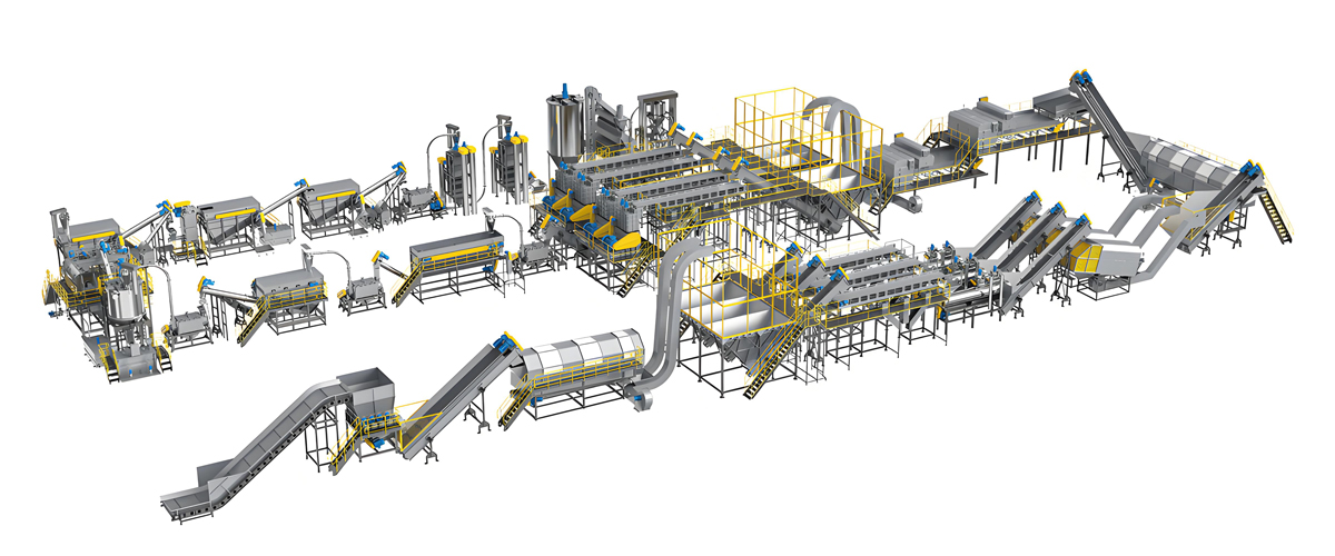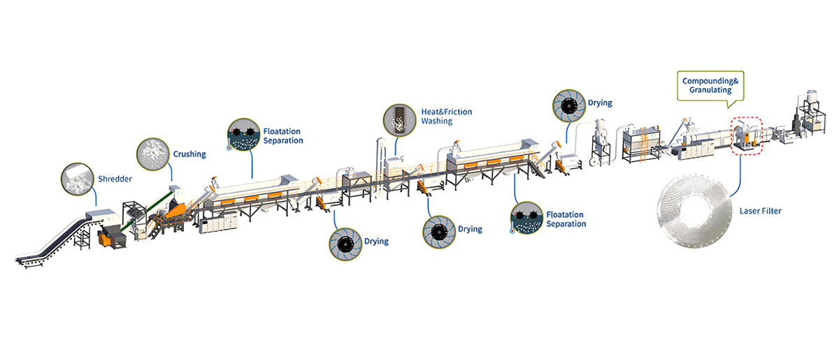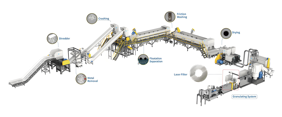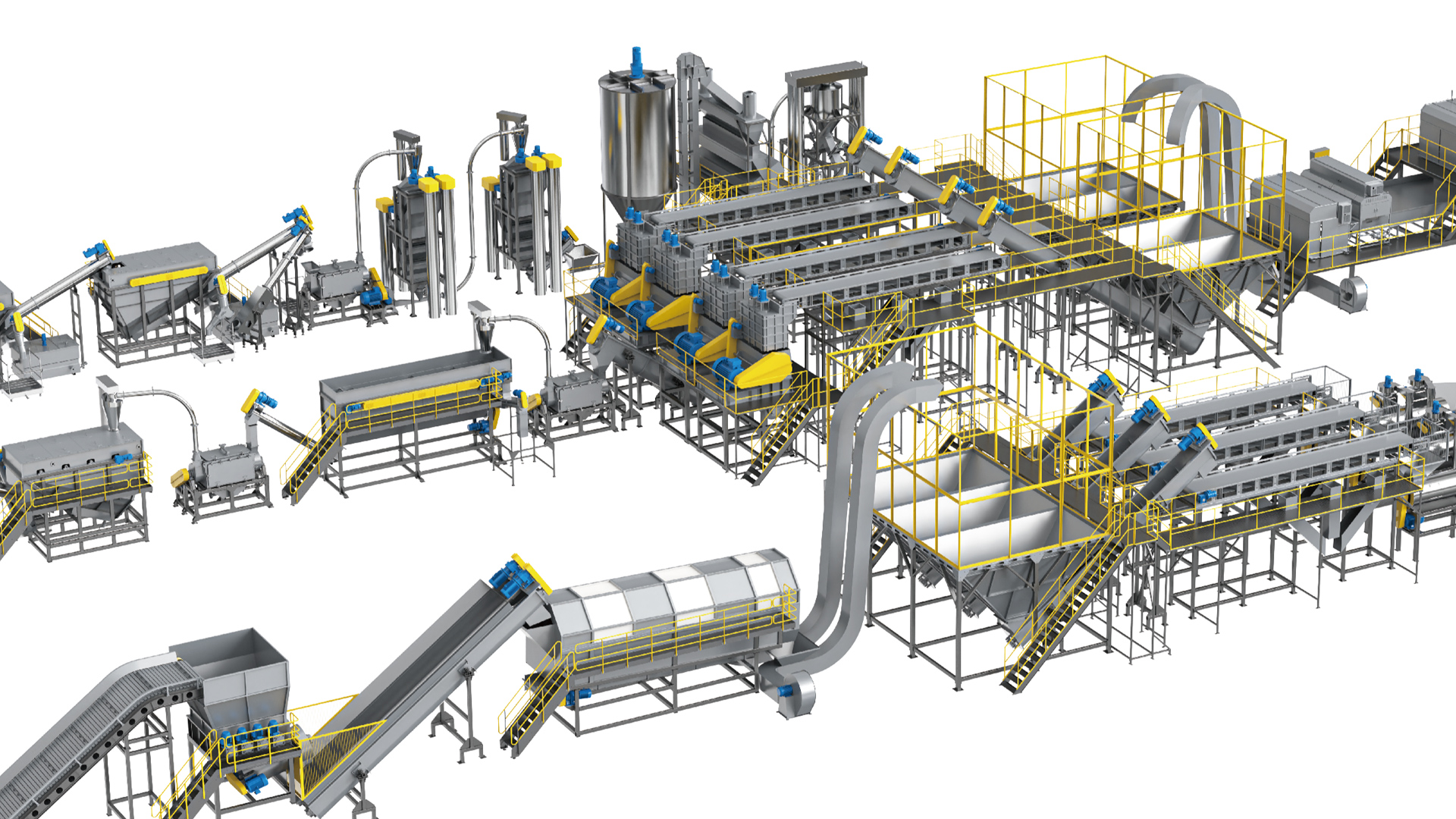

Choosing the best PP PE pelletizing line for a recycled flake to granule process is fundamentally a materials engineering decision disguised as a machinery purchase. Two lines with identical nameplate throughput — say 800 kg/h of washed polypropylene flake — can deliver granules that differ by a full melt flow index point, by 40 percent in unnotched impact energy, and by an entire commercial grade in odour rating. The difference does not live in the motor rating or the barrel length alone. It lives in how the line manages shear history, residence time distribution, moisture removal, particulate filtration and thermal exposure between the moment a flake enters the feed throat and the moment a granule leaves the dewatering centrifuge. In 2026, with post-consumer recyclate content mandates tightening across packaging, automotive interior and construction sectors, buyers are no longer able to treat re-granulation as a commodity step. The granule is the product, and the pelletizing line is the process that determines whether that product sells into a low-value bulk application or into a specified, certified, colour-consistent compound.
This guide walks through the full specification logic used by Polyretec, a Wanplas factory that has manufactured plastic recycling equipment since 2010 and established its brand identity in 2017, combining Austrian process technology with Chinese manufacturing capability. It covers feedstock classification, extruder architecture, screw geometry, force feeding and agglomeration, vacuum devolatilisation, melt filtration, cutting method selection, drying, melt flow control and the certification landscape that governs recycled polyolefin granules. The intent is not to sell a single configuration but to give a plant engineer or purchasing manager the vocabulary and the decision thresholds needed to compare quotations from Polyretec, EREMA, NGR, Starlinger and other suppliers on technical merit rather than on headline throughput.
Why the Flake-to-Granule Step Decides the Value of rPP and rPE
The pelletizing line is the only point in a plastic recycling plant where the polymer is fully melted, homogenised and filtered under controlled conditions. Everything upstream — shredding, washing, sink-float separation, friction drying — reduces contamination but does not change molecular structure. Everything downstream — bagging, blending, silo storage — only handles what the extruder produced. The pelletizing step therefore carries the entire burden of converting a heterogeneous flake population into a specified, repeatable granule.
Consider what arrives at the feed throat of a typical hard PP/PE regrind line. A single batch may contain injection-moulded crate fragments with a melt flow index around 8 g/10 min, blow-moulded drum wall sections at 0.3 g/10 min in the high load range, thin-wall thermoformed pieces, small quantities of talc-filled or glass-reinforced material that survived density separation, residual label adhesive, and a moisture load of 0.5 to 3 percent depending on drying efficiency. If the extruder simply melts this mixture and pushes it through a die, the resulting granule will have a wide molecular weight distribution, gel content from unmelted high-viscosity fractions, black specks from thermally degraded material trapped in dead zones, and an unpredictable shrinkage behaviour that downstream converters cannot compensate for.
A properly configured line intervenes at four points. First, it controls specific mechanical energy input so that shear heating is sufficient to melt the highest-viscosity fraction without over-shearing the lowest. Second, it applies staged vacuum so that water, monomer residues, degradation products and absorbed odour compounds leave the melt rather than being carried into the pellet. Third, it filters at a fineness matched to the end application so that hard contaminants do not become stress concentrators. Fourth, it cuts and cools the melt in a way that produces uniform pellet geometry, because bulk density variation and dust content directly affect the gravimetric dosing accuracy of every converter downstream.
The economic rule of thumb across the recycling industry is that a one-grade improvement in granule specification — for example moving from a general purpose rPE suitable only for thick-wall pipe cores to a filtered, deodorised rPE accepted for blown film — changes the addressable market for that output far more than a 10 percent increase in line throughput. Specify for grade first, capacity second.
Classifying the Feedstock Before Specifying the Line
No supplier can recommend a correct configuration without a feedstock classification. The single most common cause of dissatisfaction with a recycling pelletizing line is a mismatch between the bulk density and moisture profile that the buyer actually has and the profile the line was designed around. Polyolefin recyclate splits into four broad process classes, each with distinct feeding, degassing and filtration requirements.
Class A: Soft PP/PE Film and Woven Material
LDPE and LLDPE agricultural film, printed shopping bags, stretch film, PP woven bags and non-woven fabric all share a very low bulk density, typically 20 to 60 kg/m³ as loose flake and 120 to 300 kg/m³ after compaction. Surface-to-volume ratio is extreme, so washed film retains 6 to 15 percent surface moisture even after mechanical drying. Printing inks contribute solvent residues and pigment loading. This class demands compaction or agglomeration ahead of the extruder, aggressive multi-stage vacuum, and a filtration system sized for high ash content.
Class B: Rigid PP/PE Regrind
Crates, caps and closures, drums, jerrycans, pipe offcuts and injection-moulded housings produce regrind at 250 to 450 kg/m³ with residual moisture typically under 1 percent after centrifugal drying. Feeding is straightforward by gravity, degassing requirements are moderate, and the dominant challenge is melt homogenisation across a wide viscosity distribution plus filtration of metal fines and residual paper fibre.
Class C: Mixed and Lightly Contaminated Post-Consumer Streams
Kerbside mixed polyolefin bales after sorting contain a PP/PE ratio that fluctuates batch to batch, along with small fractions of PS, PET, PA barrier layers and elastomer. These streams require compatibilisation, tighter filtration, and often a twin screw architecture that permits side dosing of impact modifiers and compatibilisers.
Class D: Industrial Post-Industrial Scrap
Clean edge trim, purge material, sprues and runners from a known process. Moisture near zero, contamination near zero, viscosity narrow. This class justifies the simplest and most energy-efficient configuration and is the only class where a plain single screw line with a manual plate screen changer remains defensible.
Feedstock-to-Configuration Matrix
| Feedstock Class | Bulk Density (kg/m³) | Inlet Moisture | Recommended Extruder | Feeding Method | Vacuum Stages | Filtration Fineness |
|---|---|---|---|---|---|---|
| A — Soft film, woven, non-woven | 20–60 loose / 120–300 compacted | 6–15 percent | Single screw 36:1 with cutter-compactor, or co-rotating twin screw 44:1 | Cutter-compactor or agglomerator plus force side feeder | 2–3 | 90–150 μm |
| B — Rigid regrind (crates, caps, drums) | 250–450 | 0.3–1.0 percent | Single screw 33:1–36:1, or two-stage system | Gravity hopper with vibrating level control | 1–2 | 120–250 μm |
| C — Mixed post-consumer polyolefin | 150–350 | 1–5 percent | Co-rotating twin screw 40:1–48:1 | Gravimetric main feeder plus force side feeder for additives | 2–3 | 80–150 μm |
| D — Clean post-industrial scrap | 300–500 | Below 0.2 percent | Single screw 30:1–33:1 | Gravity hopper | 0–1 | 150–250 μm |
Extruder Architecture: Single Screw, Two-Stage and Co-Rotating Twin Screw
Extruder architecture is the highest-leverage decision in the entire specification. It determines residence time distribution, degassing capability, the ability to dose additives, the specific energy consumption per kilogram, and ultimately the achievable granule grade. Three architectures dominate the recycled polyolefin market.
Single Screw with Degassing
A grooved-feed or smooth-bore single screw extruder with a barrier screw and one or two vent ports remains the workhorse for clean rigid regrind and for film lines fed through a cutter-compactor. Diameters from 90 mm to 180 mm cover throughputs from roughly 200 to 1500 kg/h. Specific energy consumption for PE typically falls between 0.16 and 0.24 kWh/kg, which is the lowest of the three architectures. The screw runs at 60 to 130 rpm. Residence time is relatively long and the distribution is broad, which is acceptable for thermally stable polyolefins but limits the ability to run heat-sensitive additives.
The limitation of a single screw is degassing efficiency. A vent port on a single screw relies on a decompression zone that exposes only a fraction of the melt surface to vacuum, and surface renewal rate is modest. For film with 10 percent inlet moisture, one vent is rarely enough; two vents plus a well-designed pre-drying step become necessary.
Two-Stage Extrusion System
A two-stage arrangement uses a primary extruder to melt and homogenise, followed by a second, shorter, larger-diameter extruder that receives the melt at low pressure and provides an extended devolatilisation zone before building pressure for the filter and die. The primary machine can run at higher screw speed for mixing while the secondary machine runs slow and cool, decoupling mixing intensity from pumping stability. This is a strong configuration for heavily printed film, for material with high volatile load, and for lines that need very stable melt pressure at the die for underwater pelletizing.
Two-stage systems typically add 15 to 25 percent to capital cost relative to a comparable single-stage machine and add roughly 0.02 to 0.05 kWh/kg to specific energy, but they can lift residual volatile content substantially and stabilise melt pressure fluctuation to within a narrow band, which directly improves pellet size uniformity.
Co-Rotating Twin Screw
Co-rotating intermeshing twin screw extruders provide the highest degassing capability, the narrowest residence time distribution, and full modularity of screw configuration. Wanplas’s Kerke factory manufactures the KTE series of parallel co-rotating twin screw extruders, from laboratory KTE-16B units to production KTE-135D machines, and these integrate directly with Polyretec washing and pelletizing systems where a compounding-grade output is required.
The value of a twin screw in recycling is not raw throughput per unit of motor power — a single screw wins that comparison. The value is control. Kneading blocks with defined stagger angles apply distributive and dispersive mixing exactly where needed. Multiple vent positions are available along the barrel. Side feeders introduce fillers, chain extenders, compatibilisers or fresh virgin resin downstream of the melting zone so that heat-sensitive components experience minimal thermal history. Specific energy for a recycling twin screw generally runs 0.22 to 0.35 kWh/kg for polyolefins, and screw speeds range from 200 to 600 rpm depending on the torque class and the shear sensitivity of the formulation.
Architecture Comparison
| Criterion | Single Screw | Two-Stage System | Co-Rotating Twin Screw |
|---|---|---|---|
| Typical L/D | 30:1 to 36:1 | Stage 1 at 30:1, Stage 2 at 10:1 to 14:1 | 40:1 to 52:1 |
| Screw speed range | 60–130 rpm | 80–140 rpm stage 1, 25–60 rpm stage 2 | 200–600 rpm |
| Specific energy, polyolefin | 0.16–0.24 kWh/kg | 0.20–0.28 kWh/kg | 0.22–0.35 kWh/kg |
| Max practical vacuum stages | 1–2 | 2–3 | 3–4 |
| Residence time distribution | Broad | Moderate | Narrow |
| Additive side dosing | Limited, feed throat only | Possible at inter-stage | Excellent, multiple positions |
| Best-fit feedstock class | B and D | A and B | A and C |
| Relative capital cost | Low | Medium | High to Very High |
| Relative maintenance cost | Low | Medium | High |
Screw Geometry: L/D Ratio, Compression Ratio and Mixing Elements
Screw geometry translates architecture into actual process behaviour. Two extruders of the same diameter and L/D can behave completely differently depending on flight depth profile, compression ratio, barrier design and mixing section placement.
L/D Ratio Selection
Length-to-diameter ratio determines how much barrel length is available to divide among conveying, melting, mixing, devolatilisation and pumping. A 30:1 single screw dedicates roughly 8D to feed, 10D to compression and melting, 4D to a vent decompression zone, 4D to remelting after the vent and 4D to metering. Adding a second vent requires another 6D to 8D, which is why film re-granulation lines settle at 36:1 rather than 30:1.
On co-rotating twin screws, 40:1 is the practical minimum for a recycling duty with one vacuum stage. 44:1 accommodates two vacuum stages comfortably. 48:1 to 52:1 becomes necessary when three vacuum stages are combined with side feeding of filler or compatibiliser, since each side feed position consumes 4D to 6D for re-conveying and re-melting.
Compression Ratio
Compression ratio — the ratio of feed section channel volume to metering section channel volume — must match the bulk density of the incoming flake. This is where generic screws fail on recyclate. A virgin pellet screw designed around a 550 kg/m³ feed has a compression ratio of 2.5:1 to 3:1. Feed it 200 kg/m³ regrind and the metering section starves, output surges, and melt pressure oscillates.
| Feed Bulk Density (kg/m³) | Recommended Compression Ratio | Typical Feed Flight Depth (Ø120 mm screw) | Notes |
|---|---|---|---|
| Below 150 (loose film flake) | 4.0:1 to 5.0:1 | 18–22 mm | Only viable with cutter-compactor pre-densification; otherwise bridging |
| 150–250 (compacted film, woven) | 3.5:1 to 4.2:1 | 15–19 mm | Grooved feed bush strongly recommended |
| 250–350 (light rigid regrind) | 3.0:1 to 3.6:1 | 13–16 mm | Standard barrier screw performs well |
| 350–500 (dense regrind, granulate) | 2.6:1 to 3.0:1 | 11–14 mm | Watch for over-shear on PP with narrow MWD |
Mixing and Melting Elements
For rPE, a barrier screw with a Maddock or spiral shear mixer near the end of the metering section is normally sufficient to eliminate unmelt. For rPP, which has a sharper melting transition, a barrier screw with a pineapple or pin mixer gives better distributive mixing of pigment residues without excessive shear heating. On twin screws, the melting section is built from forward-conveying elements followed by a kneading block sequence at 45 and 90 degree stagger; a 90 degree block gives maximum dispersive energy but also maximum local temperature rise, so on shear-sensitive PP recyclate the sequence is usually shifted towards 30 and 45 degree blocks with a single 90 degree block for final dispersion.
Feeding the Extruder: Force Side Feeders, Compactors and Film Agglomerators
Feeding is the step where the largest number of recycling pelletizing lines underperform their nameplate rating. An extruder cannot process material it cannot swallow. When bulk density falls below roughly 200 kg/m³, gravity feeding becomes unreliable because the flake bridges in the hopper and the screw channel cannot be filled consistently.
Force Side Feeders
A force side feeder is a twin-screw stuffer mounted on the barrel that mechanically pushes low-bulk-density material into the main screw channel against the pressure of the melt seal. On co-rotating twin screw recycling lines, force side feeding raises the achievable throughput on 150 kg/m³ film flake by 40 to 70 percent compared with gravity feeding alone. The side feeder screws typically run at 150 to 400 rpm with an independent drive of 5.5 to 22 kW depending on the main extruder size. A vent on the side feeder housing is essential, otherwise entrained air travels forward with the flake and causes surging.
Cutter-Compactors
A cutter-compactor is a vertical vessel with a high-speed rotating knife assembly that simultaneously cuts, frictionally heats and densifies film. Material is heated to just below its softening point — typically 70 to 95 °C for LDPE and 95 to 120 °C for PP — so that it agglomerates into a free-flowing crumb while the frictional heat drives off surface moisture. The compactor discharges tangentially straight into the extruder feed opening, so the screw sees pre-densified, pre-dried, pre-warmed material. This combination is the reason a well-engineered compactor-fed single screw line can compete with a twin screw on film duty at lower specific energy.
Critical control parameters are rotor tip speed, blade-to-wall clearance and temperature setpoint. Too much frictional heat produces partially melted lumps that jam the discharge; too little produces material that is still fluffy and bridges. Modern compactors regulate motor load and inject a controlled water mist for evaporative cooling to hold the crumb temperature within a narrow window.
Film Agglomerators
A standalone agglomerator performs a similar densification function in batch mode, converting film scrap into a dense crumb at 300 to 400 kg/m³ that can be stored, blended and fed to a conventional extruder later. Agglomeration is useful when film scrap arrives intermittently and the pelletizing line must run continuously on a blended feed. The trade-off is an additional thermal history cycle, which slightly reduces the molecular weight of the final granule, and additional handling.
Practical guidance from Polyretec project engineering: if the feedstock is predominantly film below 150 kg/m³ and the line must run continuously above 500 kg/h, a cutter-compactor is not an optional accessory — it is the determining component of the whole line, and the extruder should be selected around it rather than the other way round.
Multi-Stage Vacuum Devolatilisation, Odour and VOC Control
Devolatilisation is the single most important quality-determining subsystem in a modern PP PE pelletizing line, and it is the subsystem most often under-specified in low-cost quotations. Recycled polyolefin melt carries water, residual monomers and oligomers, thermal degradation products such as aldehydes and ketones, printing ink solvents, adhesive residues, and absorbed odour compounds from the material’s prior life as food or detergent packaging.
How Vacuum Devolatilisation Works
Volatile removal from a polymer melt is diffusion-limited. The driving force is the difference between the partial pressure of the volatile in the melt and in the vapour space. The rate depends on melt surface area exposed, on surface renewal frequency, and on residence time under vacuum. A vent port on a screw achieves surface renewal because the screw flights continuously fold new melt to the surface. This is why twin screws devolatilise better than single screws — the intermeshing geometry renews surface far more frequently.
Practical vacuum levels used in polyolefin recycling range from a light 30 to 60 kPa absolute on an atmospheric-assist vent, down to 1 to 5 kPa absolute on a deep vacuum stage using a liquid-ring or dry-running vacuum pump with a pre-condenser. The last stage before the melt pump should always be the deepest, because the concentration gradient available at low residual volatile content is small.
Vacuum Stage Design Table
| Stage | Position (L/D from feed) | Absolute Pressure | Primary Target | Pump Type |
|---|---|---|---|---|
| Atmospheric vent | 14D–18D | Ambient | Entrained air, bulk steam flash | None, open stack with condensate trap |
| Vacuum stage 1 | 24D–28D | 20–50 kPa | Bulk moisture down to roughly 0.1 percent | Liquid ring with water separator |
| Vacuum stage 2 | 32D–38D | 3–15 kPa | Solvent residues, low molecular weight oligomers | Liquid ring with booster, pre-condenser fitted |
| Vacuum stage 3 (odour duty) | 40D–46D | 1–5 kPa | Aldehydes, ketones, fatty acid residues, odour carriers | Dry screw pump or roots booster set |
Stripping Agents and Odour Reduction
When deep vacuum alone cannot reach the target odour rating, a stripping agent is injected into the melt upstream of the final vacuum stage. Nitrogen or water injected at 0.2 to 1.0 percent by mass creates bubbles that dramatically increase the interfacial area available for mass transfer, carrying volatiles out with them. Water stripping is common on rPE film lines because water is cheap and readily condensed out of the vacuum stream; nitrogen stripping is preferred where oxidative degradation must be avoided.
Odour is assessed by trained sensory panels on a graded scale, and the target depends on the end use. Rubbish bags and construction film tolerate a high rating. Non-food consumer packaging typically demands a mid rating. Cosmetic and personal-care packaging demands the lowest achievable ratings, which in practice requires a combination of hot-alkaline washing upstream, three-stage vacuum with stripping in the extruder, and post-pelletizing deodorising in a heated silo with counterflow air for several hours at 70 to 90 °C.
Melt Filtration: Alterador de Tela Types and Filtration Fineness
Melt filtration determines the contamination class of the finished granule and therefore its saleable grade. The choice is governed by contamination load, required fineness, acceptable material loss and how much process interruption the line can tolerate.
Manual and Hydraulic Plate Alterador de Telas
A single-plate manual changer is only acceptable on clean post-industrial scrap. A hydraulic slide-plate changer with two or four screen cavities allows a screen pack to be exchanged without stopping the extruder, though a short pressure disturbance is unavoidable. Backflush versions divert a portion of clean melt backwards through the dirty cavity to dislodge the contamination cake, extending screen life significantly. Practical fineness for hydraulic plate changers on recyclate is 120 to 250 μm, and they suit contamination loads up to roughly 0.5 percent by mass.
Continuous Belt Alterador de Telas
A belt-type filter advances a roll of woven screen mesh across the melt channel, either on demand when differential pressure rises or continuously at a slow index rate. Because the screen is never removed and reinstalled, melt pressure stays essentially constant, which is critical for lines feeding a gear pump and underwater pelletizer. Belt changers handle high contamination loads economically — they are the standard choice on heavily contaminated agricultural film — and typically operate between 100 and 300 μm. The consumable cost of the screen roll is the main operating consideration.
Self-Cleaning Rotary and Laser-Drilled Filters
Self-cleaning filtration uses a perforated rotating drum or a set of laser-drilled candles with a scraper and discharge screw that continuously removes the contamination cake and expels it as a concentrated purge. These systems reach 60 to 150 μm reliably, run for weeks without operator intervention, and hold pressure variation to a very narrow band. They represent the Premium tier of filtration and are specified when the output must qualify for blown film, thin-wall injection moulding, fibre or food-contact-adjacent applications.
Filtration Selection Table
| Filter Type | Practical Fineness | Max Contamination Load | Pressure Stability | Melt Loss | Relative Cost | Typical Application |
|---|---|---|---|---|---|---|
| Manual plate changer | 200–400 μm | Below 0.05 percent | Poor, line stop required | Very low | Low | Clean post-industrial scrap |
| Hydraulic slide-plate, dual piston | 120–250 μm | Up to 0.5 percent | Moderate, brief disturbance on change | Low | Medium | Rigid regrind, caps and closures |
| Hydraulic with backflush | 100–200 μm | Up to 1.5 percent | Good | Medium | High | Mixed post-consumer polyolefin |
| Continuous belt screen changer | 100–300 μm | Up to 3 percent | Very good | Low, screen consumable instead | High | Agricultural film, heavily soiled feed |
| Self-cleaning rotary / laser-drilled candle | 60–150 μm | Up to 5 percent | Excellent, near constant | Medium to high purge rate | Premium | Film grade rPE, fibre grade rPP |
Pelletizing Method: Strand, Water Ring and Underwater Cutting
The cutting method sets pellet geometry, dust content, bulk density and the achievable ceiling on line throughput. All three common methods are viable for recycled polyolefin, and the correct choice depends on melt viscosity, throughput and the pellet specification demanded by the customer.
Strand Pelletizing
Melt is extruded through a multi-hole strand die into a water bath or across a cooling conveyor, then drawn through a pair of feed rolls into a rotating cutter. Pellets are cylindrical, typically 2.5 to 4 mm diameter and 3 to 5 mm long. Strand cutting produces the most uniform pellet with the lowest fines content and gives the operator direct visual confirmation of melt quality — a strand that breaks or shows bubbles instantly reveals a filtration or degassing problem.
The limitation is that strands must be stable enough to convey. Low viscosity recyclate with a melt flow index above roughly 15 g/10 min tends to sag and break. Strand systems also require operator attention at start-up and after every screen change, and they occupy considerable floor length. Typical practical range is 150 to 1500 kg/h.
Water Ring Pelletizing
A rotating blade assembly cuts the melt directly at the face of an annular die, and the pellets are immediately thrown into a ring of water circulating inside the cutting chamber housing. Because cutting occurs at the die face, there is no strand to break, which makes water ring cutting far more tolerant of viscosity variation and of the start-up transients that are routine in recycling. Pellets are lens- or barrel-shaped and slightly less uniform than strand pellets.
Water ring systems are the most widely used method on PP/PE recycling lines in the 300 to 2000 kg/h band because they combine robustness, moderate cost and easy automation. Blade-to-die contact pressure is adjusted by a spring or pneumatic loading system, and blade life on abrasive filled recyclate is a real operating consideration.
Underwater Pelletizing
In underwater pelletizing the die face is fully submerged in a temperature-controlled water chamber and the cutter runs inside that chamber. Pellets are perfectly spherical, dust content is the lowest of the three methods, and the system scales cleanly above 2000 kg/h. Underwater cutting requires a melt pump for pressure stability, a heated and insulated die plate to prevent freeze-off, and a start-up bypass valve. It is the most capital-intensive and the most control-intensive option, and it is normally justified where pellet sphericity matters for downstream gravimetric dosing or where throughput exceeds what a water ring can handle.
Pelletizing Method Comparison
| Attribute | Strand Pelletizing | Water Ring Pelletizing | Underwater Pelletizing |
|---|---|---|---|
| Pellet shape | Cylindrical, 2.5–4 mm dia | Lens / barrel, 3–5 mm | Spherical, 2–4 mm |
| Practical throughput | 150–1500 kg/h | 300–2000 kg/h | 500–6000 kg/h |
| Melt flow index tolerance | 0.3–15 g/10 min | 0.2–40 g/10 min | 0.2–60 g/10 min |
| Fines and dust content | Low | Medium | Very low |
| Start-up complexity | Manual strand threading | Simple, semi-automatic | Complex, bypass and die heating required |
| Melt pump required | Optional | Recommended | Mandatory |
| Floor space demand | High (long bath) | Low | Medium |
| Relative capital cost | Low | Medium | Very High |
Dewatering, Drying and Pellet Conditioning
Wet pellets leaving a water ring or underwater cutter carry 8 to 20 percent surface water. Achieving the residual moisture target that converters demand — generally below 0.1 percent for rPE and below 0.05 percent for rPP intended for injection moulding — requires a two-stage approach.
The first stage is mechanical. A centrifugal dryer, essentially a vertical perforated basket with a high-speed rotor spinning at 1200 to 1800 rpm, throws water outward through the screen while pellets travel upward on a helical path. A well-sized centrifugal dryer reduces surface moisture from around 15 percent to 0.3 to 0.8 percent in a residence time of only a few seconds. Screen slot width is typically 0.6 to 1.2 mm; too wide and pellets escape into the water circuit, too narrow and the screen blinds with fines.
The second stage is thermal. A fluid-bed or vibrating hot-air dryer at 60 to 90 °C removes the remaining film of water. For rPP this stage doubles as a crystallisation conditioning step, allowing the pellet to reach a stable crystalline morphology before storage so that bulk density stabilises. Where deodorising is required, this thermal stage is extended into a dedicated conditioning silo with counterflow air for 4 to 12 hours.
Pellet classification follows drying. A vibrating classifier with an upper deck at roughly 6 mm and a lower deck at roughly 1.5 mm removes oversize agglomerates and fines. Fines content above 0.5 percent by mass causes bridging in converter hoppers and inconsistent gravimetric dosing, so classification is not optional on a commercially graded product.
MFI Control, Degradation and Property Restoration
Every pass through an extruder changes the molecular architecture of a polyolefin. Understanding the direction and magnitude of that change is what allows a recycler to hit a melt flow index specification consistently.
Divergent Behaviour of PP and PE
Polypropylene degrades predominantly by chain scission under combined thermal and shear stress in the presence of trace oxygen. Molecular weight falls and melt flow index rises. A typical rPP can gain 15 to 40 percent in melt flow index across a single pelletizing pass if the process is not controlled, and considerably more if the material was already thermally abused in its first life.
Polyethylene, particularly LDPE and LLDPE, tends towards crosslinking and long-chain branching under the same conditions. Molecular weight rises, melt flow index falls, and gel content increases. An rLDPE film line that shows rising die pressure and increasing gel counts over a production campaign is almost always experiencing progressive crosslinking, usually because oxygen ingress at the feed throat or an inadequate vacuum seal is allowing oxidative reactions.
Control Levers
- Melt temperature ceiling. Hold rPP melt below 235 °C and rPE below 225 °C wherever the process allows. Every 10 °C above these thresholds roughly doubles the oxidative degradation rate.
- Specific mechanical energy. Reduce screw speed and increase feed rate to lower specific energy input. On a twin screw, replacing one 90 degree kneading block with a 45 degree block can cut local shear heating measurably.
- Oxygen exclusion. Nitrogen blanketing of the feed hopper is inexpensive and effective, particularly for rPP.
- Stabiliser packages. A combination of primary hindered phenolic antioxidant and secondary phosphite processing stabiliser, dosed at 0.1 to 0.5 percent, restores the depleted stabiliser reservoir of post-consumer material. Acid scavengers such as calcium stearate or hydrotalcite neutralise catalyst residues and halogen traces from contaminated feed.
- Chain extenders. Multifunctional epoxy-functional oligomeric chain extenders, dosed typically at 0.2 to 1.0 percent, react with chain-end groups to rebuild molecular weight. On rPP they reduce melt flow index and restore melt strength; on rPET-contaminated polyolefin blends they also improve interfacial adhesion.
- Compatibilisers. For mixed PP/PE streams, maleic-anhydride-grafted polyolefins or ethylene-propylene block copolymer compatibilisers at 2 to 8 percent dramatically improve the impact strength of the blend by reducing the domain size of the dispersed phase. Without compatibilisation, a 70/30 PP/PE blend behaves as a notch-sensitive material with poor low-temperature performance.
Batch-to-Batch Consistency
Property restoration is only meaningful if it is repeatable. The practical instruments are an inline melt viscometer or a rheological melt pressure signal correlated to melt flow index, laboratory melt flow index testing on every production shift, and a feedstock blending strategy that homogenises incoming bales before they reach the line. Many mature recyclers operate a pre-blending silo holding 8 to 24 hours of feed so that upstream compositional swings are averaged out before they can propagate into granule specification variance.
Certificação and Compliance for Recycled PP and PE Granules
Certificação determines which markets a granule can enter, and increasingly determines whether an offtake contract is even negotiable. Buyers should specify the target certification at the enquiry stage, because several requirements have direct hardware implications.
| Scheme or Standard | Scope | Implication for the Linha de pelletização |
|---|---|---|
| EuCertPlast | European certification of post-consumer plastic recyclers, traceability and input verification | Requires documented mass balance, batch traceability from bale to granule, calibrated weighing at infeed and outfeed |
| GRS (Global Recycled Standard) | Recycled content claim, chain of custody, social and environmental criteria | Segregated storage and clearly separated production campaigns, restricted substance controls on additives dosed at the extruder |
| ISO 15270 | Guidelines for recovery and recycling of plastics waste, terminology and process framework | Provides the definitional basis for describing mechanical recycling routes in technical documentation and tender responses |
| EU 2022/1616 | Recycled plastic materials and articles intended to come into contact with foods | Requires an authorised decontamination technology with demonstrated challenge-test performance; for polyolefins this typically means a super-clean process route with validated deep vacuum devolatilisation |
| ISO 9001 | Quality management system | Documented control plan for melt flow index, ash, moisture, colour and odour on each batch |
| CE marking | Machinery safety for equipment placed on the European market | Guarding, emergency stop category, interlocked access to cutter chamber and die area, documented risk assessment |
Test methods that recur in customer specifications include ASTM D1238 and ISO 1133 for melt flow index, ISO 3451 for ash content, ISO 1183 for density, ISO 179 and ISO 180 for impact, and ISO 527 for tensile properties. A recycler bidding into automotive or appliance supply chains should expect to report all of these on a per-batch certificate of analysis.
Capacity Planning, Utilities and Relative Cost Grading
Line sizing should be driven by annual tonnage divided by realistic operating hours, not by peak instantaneous throughput. A recycling line rarely achieves better than 80 to 88 percent availability once screen changes, blade changes, feedstock transitions, cleaning and planned maintenance are counted. A plant targeting 4000 tonnes per year on two shifts, 300 days, at 85 percent availability needs a nominal capacity of roughly 4000000 divided by (300 × 16 × 0.85), which is close to 980 kg/h — so a 1000 to 1200 kg/h nominal line, not an 800 kg/h line.
| Nominal Capacity | Typical Extruder Size | Main Drive Power | Total Connected Load | Cooling Water Demand | Footprint (approx.) | Relative Investment Tier |
|---|---|---|---|---|---|---|
| 300–500 kg/h | Ø110–Ø130 single screw | 90–132 kW | 160–220 kW | 10–16 m³/h | 18 × 5 m | Low |
| 500–800 kg/h | Ø130–Ø150 single screw or Ø75 twin | 132–200 kW | 230–320 kW | 16–24 m³/h | 22 × 6 m | Medium |
| 800–1200 kg/h | Ø150–Ø160 single screw or Ø92 twin | 200–280 kW | 330–450 kW | 24–34 m³/h | 26 × 7 m | High |
| 1200–2000 kg/h | Ø180 single screw or Ø110–Ø135 twin | 280–450 kW | 450–700 kW | 34–50 m³/h | 32 × 8 m | Very High |
Operating cost is dominated by electricity, screen or filter consumables, blade regrinding, cooling water treatment and labour. Energy per kilogram is the metric worth negotiating hardest, because it compounds over the life of the asset. A difference of 0.05 kWh/kg on a line running 4000 tonnes per year represents 200000 kWh annually — a figure that dwarfs most differences in purchase price over a five-year horizon.
Key operating benchmarks for a well-run PP PE pelletizing line: total specific energy including auxiliaries between 0.28 and 0.45 kWh/kg; melt filtration purge loss below 1.5 percent of throughput; pellet fines below 0.3 percent by mass; residual moisture below 0.08 percent; melt flow index batch-to-batch variation within plus or minus 12 percent of nominal.
Frequently Asked Questions
Should I choose a single screw or twin screw extruder for a PP PE pelletizing line?
Single screw and two-stage single screw machines suit clean, sorted, low-moisture PP or PE flake where the goal is simple re-granulation at the lowest specific energy. Their specific energy consumption of 0.16 to 0.24 kWh/kg is materially lower than a twin screw, and the screws and barrels are less expensive to replace. Co-rotating twin screw extruders suit contaminated, mixed, high-moisture or heavily printed post-consumer streams, where devolatilisation capacity, additive dosing flexibility and compatibilisation matter more than the lowest possible energy figure. If your feedstock is a single, stable, known stream, buy the single screw. If your feedstock varies week to week and you need to sell a specified compound rather than a commodity granule, buy the twin screw.
What filtration fineness is required for recycled PP and PE pellets?
General purpose rPP and rPE destined for injection moulding or thick-wall extrusion is normally filtered between 150 and 250 μm. Blown film and blow moulding grades typically require 90 to 150 μm. Thin gauge film below 30 μm and fibre grades need 60 to 90 μm, which almost always demands a continuous laser-drilled or self-cleaning candle filter with backflush rather than a simple plate changer. Remember that finer filtration raises melt pressure, increases purge loss and shortens screen life, so specifying finer than the application needs is a direct and permanent operating cost penalty.
How many vacuum stages does a recycling pelletizing line really need?
One atmospheric vent plus one vacuum stage is adequate for clean washed rigid regrind with residual moisture below 1 percent. Printed film, agricultural film and odour-critical applications generally require two or three vacuum stages, with the last stage held between 1 and 5 kPa absolute so that low molecular weight volatiles and residual solvents are drawn off before the melt reaches the melt pump. Adding a vacuum stage retroactively is expensive because it requires additional barrel length, so specify the stage count for the worst feedstock you expect to run, not the average.
Why does my recycled PP granule have a higher melt flow index than the input flake?
Polypropylene degrades by chain scission under combined heat, shear and trace oxygen exposure, which reduces average molecular weight and therefore raises melt flow index. The main contributors are melt temperature above 235 °C, excessive specific mechanical energy from running high screw speed at partial fill, oxygen entering through the feed throat, and depleted antioxidant reserves in the post-consumer feed. The remedies in order of effectiveness are lowering melt temperature, reducing screw speed while increasing feed rate, nitrogen blanketing the hopper, dosing a phenolic plus phosphite stabiliser package at 0.1 to 0.5 percent, and adding an epoxy-functional chain extender at 0.2 to 1.0 percent to rebuild molecular weight.
Can one line process both soft film and rigid regrind?
Yes, but only with deliberate design compromises. A dual-duty line needs a cutter-compactor with a bypass so that rigid regrind can be gravity-fed directly to the extruder, a screw compression ratio chosen as a compromise around 3.4:1 to 3.8:1, and a filtration system sized for the dirtier of the two streams. Expect throughput on the rigid stream to be 10 to 20 percent below what a dedicated rigid line would achieve, and expect a changeover purge of 20 to 60 minutes between campaigns. If both streams represent substantial annual tonnage, two dedicated lines usually outperform one flexible line on total output and granule consistency.
What causes black specks in recycled polyolefin granules?
Black specks come from four sources: carbonised polymer accumulating in dead zones such as die adapters, screen changer cavities and worn screw flight clearances; foreign contamination such as rubber or thermoset particles that survive filtration; degraded material re-entrained after a long production stop; and residual pigment agglomerates from dark-coloured input. The diagnostic sequence is to first check whether specks appear immediately after start-up (suggesting dead-zone accumulation) or progressively during a run (suggesting continuous contamination). Streamlined flow-channel design, regular hot purging with a cleaning compound, and finer filtration address most cases.
How long do the screws and barrel last on a recycling extruder?
Wear life depends overwhelmingly on the ash content of the feed. On clean post-industrial polyolefin with ash below 0.3 percent, a nitrided screw and bimetallic barrel may run 25000 to 40000 hours before flight clearance exceeds tolerance. On post-consumer film with 2 to 5 percent ash including sand and mineral filler, the same components may need attention at 8000 to 15000 hours. Specifying a bimetallic barrel liner and a screw with hardfaced flight lands raises the initial cost tier from Medium to High but often doubles service life on abrasive duty, which is usually the better long-term decision.
What does a proper factory acceptance test for a pelletizing line include?
A meaningful acceptance test runs the buyer’s own feedstock, not a substitute. It should demonstrate sustained throughput at nominal rate for a continuous period of at least 8 hours, record melt temperature and pressure profiles, measure specific energy consumption in kWh/kg, sample granules at intervals for melt flow index, moisture, ash and fines, and include at least one screen change and one simulated feedstock interruption to verify recovery behaviour. Polyretec, as a Wanplas factory, operates an open factory policy and encourages customers to attend trials in person; the Wanplas brand commitments also include a transportation guarantee, a production capacity guarantee, an annual free spare parts allowance, and a quality undertaking covering refund plus additional compensation should agreed quality standards not be met.
Do I need a melt pump on my recycling line?
A gear-type melt pump decouples the extruder’s pressure-generating duty from the die, allowing the extruder to run at lower head pressure and therefore lower melt temperature, while delivering a very stable volumetric flow to the pelletizer. It is mandatory for underwater pelletizing, strongly recommended for water ring cutting above roughly 800 kg/h, and optional on strand lines. Beyond pressure stability, a melt pump typically reduces melt temperature by 5 to 12 °C and improves pellet size consistency measurably, which matters when the granule is sold on specification.
Conclusion
The best PP PE pelletizing line for a recycled flake to granule process is the one whose feeding, degassing, filtration and cutting subsystems are each matched to the specific feedstock class and the specific granule grade you intend to sell. There is no universally superior architecture. Clean rigid regrind heading into general-purpose applications is served best by a well-designed 33:1 to 36:1 single screw with a hydraulic backflush screen changer and water ring cutting. Heavily printed, low-density post-consumer film heading into film-grade rPE demands a cutter-compactor, a 40:1 or longer barrel with three vacuum stages and stripping agent injection, a continuous self-cleaning filter at 90 to 150 μm, a melt pump and underwater or water ring cutting, followed by extended thermal deodorising.
Work backwards from the granule specification. Define the target melt flow index window, ash limit, fines limit, odour rating and certification scheme first. Then let those targets dictate filtration fineness, vacuum stage count, screw configuration and cutting method. Only after that should throughput and price enter the conversation. Buyers who invert this sequence — selecting on capacity and price, then discovering that the granule cannot meet the offtake specification — account for the large majority of disappointing recycling investments.
Polyretec, a Wanplas factory operating since 2010 with more than 100 completed projects across 50 or more countries and a team of over 24 engineers, builds washing and pelletizing systems around exactly this specification logic, drawing on Austrian process technology and Chinese manufacturing capability. Where a compounding-grade output is required, Wanplas’s Kerke factory supplies KTE series co-rotating twin screw extruders that integrate directly with Polyretec washing lines and downstream pelletizing systems. Across the Wanplas brand and all of its specialised factories, the guiding commitment remains the same: deliver plastic machinery that performs to the specification the customer actually needs, verified on the customer’s own material before shipment.