
Getting clean separation in a plastic washing line often comes down to one unglamorous control point: the water level inside the sink-float separation tank. Polyretec, a Wanplas factory, has commissioned hundreds of washing lines across more than 50 countries since its origin in 2010, and the single adjustment that most often decides whether an operator ships a 99 percent pure float fraction or a contaminated mix is the floatation tank water level. This guide is written like a field-engineer manual. It explains why a few millimeters of water height change the physics of density separation, shows the four functional surfaces the level controls, gives a repeatable 7-step tuning procedure, lists the variables that must be adjusted together with the level, and provides a symptom-to-remedy fault matrix. The goal is simple: let you set, verify, and lock a water level that delivers stable separation under real, fluctuating plant conditions.
A sink-float separation tank (often called a floatation tank or float wash tank) separates plastics by density using water as the medium. Light polymers such as polyethylene and polypropylene rise to the surface and are conveyed off as the float fraction; denser polymers such as PET, PVC, and PS, plus sand, glass, and metal, sink and are dragged out by a bottom screw as the sink fraction. The water level is not a decoration. It sets the surface height, the submerged depth of the discharge screws, the quiet settling zone at the bottom, and the residence time available for particles to travel to their correct outlet. Move it by 10 mm and you can flip a PET bottle flake from “sink” to “false float.” That sensitivity is exactly why this article exists.
Before going deeper, one house rule for this whole guide: we never tune the water level alone. Feed rate, screw speed, make-up water flow, water quality, and temperature all couple with the level. Treat the level as the master dial, but always adjust it together with the supporting variables described in section 4, or the result will not hold when the shift changes and the feedstock mix shifts.
1. Physics of Floatation (Sink-Float) Separation
The separation in a floatation tank is governed by density, particle size, fluid viscosity, and surface effects. Understand these four and every water-level decision becomes predictable instead of trial-and-error.
1.1 The density window around water
Clean water at 20 degrees C has a density of 1.00 g/cm3. The float fraction is made of polymers lighter than that; the sink fraction is everything heavier. The table below lists the typical density ranges that decide which side of the water surface a particle lands on. Note the margins: low-density polyethylene and polypropylene float with comfortable margin, while polystyrene and PVC sit very close to or well above the water line, which is why they are sensitive to any change in medium density.
| Material | Typical density (g/cm3) | Behavior in water | Practical note |
|---|---|---|---|
| Low-density polyethylene (LDPE) | 0.915 to 0.925 | Floats strongly | Hard to keep submerged; easy to over-carry |
| Linear-low-density polyethylene (LLDPE) | 0.915 to 0.935 | Floats | Similar to LDPE in flotation |
| High-density polyethylene (HDPE) | 0.940 to 0.965 | Floats | Rigid items need full wetting to release trapped air |
| Polypropylene (PP) | 0.890 to 0.910 | Floats strongest | Most buoyant common recyclate |
| Polystyrene (PS) | 1.04 to 1.07 | Sinks in water | Near neutral; needs heavy medium to separate from PVC |
| Polyvinyl chloride (PVC) | 1.35 to 1.45 | Sinks | Stable sink phase |
| Polyethylene terephthalate (PET) | 1.38 to 1.40 | Sinks | Main sink product; prone to false float via bubbles |
| Sand and mineral grit | 2.5 to 2.7 | Sinks fast | Settles to bottom, must not re-suspend |
| Aluminum | 2.70 | Sinks | Removed in sink fraction or by downstream eddy current |
The takeaway for water-level work: the float versus sink decision is binary only when the medium truly sits at 1.00 g/cm3. Anything that nudges the apparent medium density upward – suspended solids, dissolved salts, temperature – silently redraws the line between float and sink. We return to this in section 4 on water quality.
1.2 Stokes settling and why particle size matters
For a spherical particle settling in a viscous fluid, the terminal velocity follows Stokes’ law:
v = (rho_p minus rho_f) x g x d squared / (18 x mu)
where v is the settling velocity, rho_p the particle density, rho_f the fluid density, g gravity, d the particle diameter, and mu the dynamic viscosity of water. Two consequences drive tank design. First, settling speed scales with the square of particle size, so a 10 mm PET regrind sinks roughly 100 times faster than a 1 mm flake of the same material. Second, the gap (rho_p minus rho_f) sets the driving force. A PET flake (1.38) in water (1.00) has a strong downward pull; a PS grain (1.05) has almost none, so it hangs in the water column and is easily mistaken for float material when surface currents are present.
This is why flat films and thin flakes behave worse than the formula predicts. A film scrap of 30 microns thickness has a huge surface-area-to-volume ratio and a shape factor far from spherical, so it is held up by drag and surface tension, drifts with currents, and can be swept to the overflow even though its bulk density says “sink.” The water level controls how much horizontal travel distance and how quiet a column the film gets before it reaches an outlet – directly addressing the shape-factor problem.
1.3 Surface tension, bubbles, and false float
The most common separation failure in a floatation tank is not a wrong density reading; it is air. PET flakes, fresh from a friction washer, carry micro-bubbles on their surfaces. Each bubble is a tiny life jacket. A PET flake that should sink is instead held at the surface and discharged with the polyethylene fraction. This “false float” is the core contradiction that water-level tuning must solve: raise the level and you give bubbles more time to detach and the flake more column to sink, but you also raise the chance of pushing light sink material toward the overflow. The standard countermeasure is a gentle surface spray or a de-aeration weir plus a correct, stable water level, never a violent agitation that would only make more bubbles.
1.4 Temperature effects
Water is not a constant medium. Heating from 20 to 45 degrees C lowers its density to about 0.990 g/cm3 and cuts viscosity by roughly 40 percent. Lower viscosity speeds settling, which is helpful, but the density drop also slightly narrows the float window and can tip near-neutral materials. In winter, cold water is more viscous, settling is slower, and the same level that worked in summer may under-separate. Plan for a level that is verified at the actual operating temperature, or add mild heating to a 25 to 35 degrees C band when the feedstock is temperature-sensitive.
2. Four Functional Faces of Water Level
A single number on the level gauge actually controls four distinct physical functions inside the tank. Thinking of them separately is the fastest way to diagnose why a change helped one fraction and hurt another.
| Functional face | What it controls | Recommended value | Failure mode if wrong |
|---|---|---|---|
| Overflow weir height | Surface elevation where float fraction and overflow water leave | 60 to 75 percent of tank depth above bottom | Too low: float fraction not cleared; too high: excessive water carry-over |
| Effective separation depth | Clear water column from surface to top of the sink screw | 300 to 600 mm | Too shallow: sink phase dragged to float outlet; too deep: wasted residence time and water |
| Discharge screw / paddle submergence | How deep the float conveyor sits below the surface | 50 to 120 mm | Too shallow: lifts excess water (dewatering load); too deep: re-suspends and entrains sink phase |
| Quiescent settling zone | Low-disturbance bottom layer for stable sinking | 150 to 250 mm | Disturbed: sink fraction re-suspends and contaminates float outlet |
2.1 Overflow weir height
The weir is the lip over which floating material and surplus water exit. Setting it at 60 to 75 percent of the total tank depth is a balance: high enough that the float fraction has a long, calm travel path to the discharge paddle, but low enough that you are not filling the tank with unused water. On Polyretec washing lines the weir is adjustable, so the level setpoint and the weir position are tuned as a pair, not independently.
2.2 Effective separation depth
This is the net clear column between the water surface and the top of the sinking-fraction screw. Below 300 mm, sink particles – especially films and small flakes – get caught in the screw’s swept zone and carried toward the float side. Above 600 mm you gain little extra separation but you pay in tank volume, water inventory, and residence time. The 300 to 600 mm band is where most PET and PP/PE washing lines settle.
2.3 Discharge screw and paddle submergence
The floating fraction is lifted by a rotating paddle or screw that dips just below the surface. Submerge it only 50 to 120 mm. Too shallow and the paddle throws a sheet of water onto the dewatering screen, raising the downstream drying load and wasting pumped water. Too deep and the paddle’s vortex pulls sinking flakes up into the float stream. The submergence is set by the water level, which is why the level dial is the real controller of this face.
2.4 Quiescent settling zone
The bottom 150 to 250 mm of the tank should be the calmest region. Sink particles need a still layer to come to rest before the bottom screw collects them. If the level is so low that the sink screw agitates this zone, or if return water is dumped too close to the bottom, sand and PET re-suspend and end up in the wrong outlet. Protect this zone as a design rule, then verify it during commissioning.
2.5 What this means on a real Polyretec line
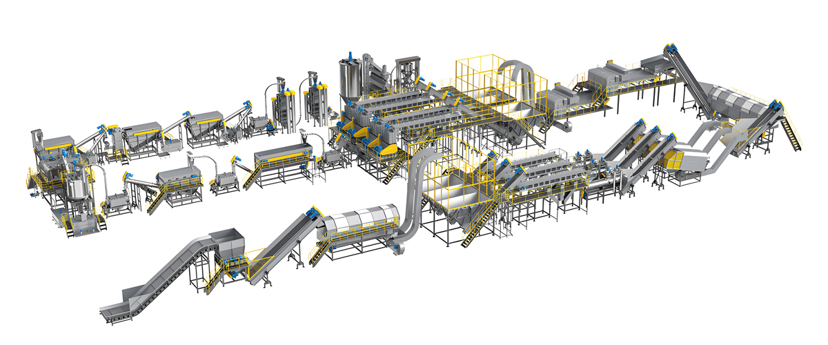
On a Polyretec food-grade PET bottle washing line, the sink-float separation stage is engineered around these four faces. The table below shows how the recommended level geometry scales with line capacity. The capacities are taken from the Polyretec washing line range; the level geometry reflects the engineering recommendations above and is fine-tuned per project during material trials.
| Specification | 500 kg/h class | 1000 kg/h class | 2000 kg/h class | 3000 kg/h class | 6000 kg/h class |
|---|---|---|---|---|---|
| Rated capacity (kg/h) | 500 | 1000 | 2000 | 3000 | 6000 |
| Sink-float separation tanks | 1 | 1 | 2 | 2 | 3 |
| Effective separation depth (mm) | 300 to 450 | 350 to 500 | 400 to 550 | 450 to 600 | 450 to 600 |
| Discharge screw submergence (mm) | 50 to 90 | 60 to 100 | 70 to 110 | 80 to 120 | 80 to 120 |
| Quiescent bottom zone (mm) | 150 to 200 | 150 to 220 | 180 to 240 | 200 to 250 | 200 to 250 |
| Float screw speed (rpm) | 6 to 12 | 7 to 14 | 8 to 16 | 9 to 18 | 10 to 18 |
| Water consumption (m3 per ton) | 0.6 to 1.0 | 0.5 to 0.9 | 0.4 to 0.8 | 0.4 to 0.7 | 0.3 to 0.7 |
| Typical installed power (kW, reference) | 120 to 180 | 200 to 280 | 350 to 480 | 520 to 700 | 850 to 1100 |
| Compliance | CE / ISO 9001 / ISO 14001 | CE / ISO 9001 / ISO 14001 (line built to Wanplas group quality system) | |||
The key message: larger lines do not just get bigger tanks, they get more tanks in series and a slightly deeper separation column. The water-level procedure in section 3 is identical regardless of size; only the per-tank setpoint and the number of stages change.
3. Step-by-Step Water Level Adjustment SOP
This is the most important, most repeatable part of the guide. Follow it literally on every new line and after every major feedstock change. The discipline that matters most is single-variable tuning: change only the water level, hold everything else, measure, record, then decide.
| Step | Action | Target / acceptance | Why it matters |
|---|---|---|---|
| 1. Empty-tank baseline | Record total tank depth, screw axis height, weir datum; fit a graduated scale and sight glass | Scale readable to 5 mm | You cannot tune what you cannot measure repeatably |
| 2. Clean-water run | Fill to 20 to 30 mm below weir; observe surface velocity | Surface velocity 0.05 to 0.15 m/s | Fast surface flow drives sink phase to the float outlet |
| 3. Low-load trial | Feed at 40 percent rated capacity; stabilize 15 to 20 min | Stable bed, no surging | Low load reveals the level window before full stress |
| 4. Three-point sampling | Take 1 kg each from float outlet, sink outlet, overflow return; dry and weigh | Compute float purity and sink carry-over | Quantifies separation instead of guessing by eye |
| 5. Single-variable trim | Adjust level plus or minus 10 mm; run 10 min; re-sample | Plot level vs purity and carry-over | Finds the crossover optimum without confounding factors |
| 6. Load-gradient check | Re-test at 60, 80, 100 percent capacity | Confirm window holds at full load | Full load thickens the bed; optimum usually drops 5 to 15 mm |
| 7. Lock and dashboard | Write setpoint to SOP and HMI; set level alarms at plus or minus 15 mm | Alarm limits active | Holds the gain and alerts before quality drifts |
3.1 Step 1: empty-tank baseline calibration
With the tank drained, measure and mark the total depth from the bottom to the weir, the height of the sink-screw axis, and the datum of the overflow lip. Fit a permanent graduated staff and a sight glass on the tank wall. Operators should be able to read the level to within 5 mm at a glance. This sounds trivial, yet most “unexplained” separation drift on used lines traces back to a level indicator nobody calibrated after a repair.
3.2 Step 2: clean-water trial run
Fill the tank to 20 to 30 mm below the weir and run the screws with no material. Drop a floating tracer (a small LDPE chip) and time its travel, or use a flow flag, to estimate surface velocity. The target is 0.05 to 0.15 m/s. Above this band, the surface current becomes a conveyor that drags sinking flakes toward the float paddle. If velocity is too high, reduce the return-water flow or adjust the circulation paddle angle before you touch the level.
3.3 Step 3: low-load material trial
Introduce feed at 40 percent of rated capacity. Let the bed stabilize for 15 to 20 minutes. The point of starting low is to open the separation window wide and find the center of it before the line is stressed. Surging feed at this stage only hides the true level effect, so use a steady, metered feed.
3.4 Step 4: the three-point sampling method
Collect three 1 kg samples: one from the float discharge, one from the sink discharge, and one from the overflow return water (the latter tells you how much fine material you are losing). Dry and weigh each, then separate by hand or density check to calculate two numbers: float purity percent (how much of the float sample is truly LDPE/PP) and sink carry-over percent (how much PET/PVC is wrongly leaving with the float). These two curves are your scoreboard for every subsequent change.
3.5 Step 5: single-variable trimming
Change the level by exactly plus or minus 10 mm, run 10 minutes, and re-sample. Plot float purity and sink carry-over against level. The optimum is the crossover point where both curves are acceptable and the gap between them is widest. Resist the urge to also change screw speed here; if you change two things at once you will never know which one fixed the problem, and the next feedstock shift will break it again.
3.6 Step 6: load-gradient verification
Repeat the sampling at 60, 80, and 100 percent of rated capacity. Expect the optimal level to move down by 5 to 15 mm at full load because the material bed is thicker and the quiet zone is more easily disturbed. Only a level validated across the full load range is safe to lock.
3.7 Step 7: lock the setpoint and alarm
Write the verified level into the line SOP and the HMI recipe. Set high and low level alarms at plus or minus 15 mm so that an upstream water-flow fault triggers an alert before product quality drops. On Polyretec lines this is stored as a named recipe, so a change of shift or a new material grade simply calls the right recipe instead of re-tuning from scratch.
4. Variables Coupled with Water Level
Tuning the level alone is like tuning only the idle speed of an engine. These supporting variables must move with the level or the separation will not hold.
| Variable | Recommended range | Coupling with water level | Symptom if mismatched |
|---|---|---|---|
| Feed rate / bed load | kg per m2 per h within tank rating | Overload defeats any level setting | Whole fraction mixes regardless of level |
| Float screw speed | 6 to 18 rpm | Faster speed needs lower level to avoid entrainment | Sink phase carried up with float |
| Sink screw speed | 3 to 10 rpm | Too slow lets sand build and re-suspend | Bottom plate-out, carry-over rises |
| Circulation paddle | Angle and speed for surface push, not down-press | Wrong angle creates down-flow that fights the level | Material pushed down instead of conveyed |
| Make-up water flow | 0.3 to 1.0 m3 per ton | Too much flow raises level and surface speed | Overflow carry, unstable level |
| Return-water inlet position | 100 to 200 mm below surface | Too deep disturbs quiescent zone | Sink phase re-suspends |
| Water quality (suspended solids) | SS below 30 g/L, medium density near 1.00 | High SS raises apparent density, fakes float | PS/PVC false float, PET loss |
| Temperature | 25 to 35 degrees C preferred | Cold water settles slowly, needs deeper level or heat | Under-separation in winter |
| Foaming | Minimal; surfactant residues controlled | Foam layer mimics a false high level | Float fraction contaminated, overflow loss |
4.1 Feed rate and bed thickness
The floatation tank has a maximum areal load in kg per square meter per hour. Exceed it and the bed is so thick that the float and sink fractions physically mix before they can separate, whatever the water level says. Size the tank to the line capacity and never push feed beyond the design load hoping the level will save you.
4.2 Screw speeds
The float transfer screw runs 6 to 18 rpm and the sink screw 3 to 10 rpm. Higher speeds mean more turbulence and more entrainment, so the higher you run the screws, the lower you must set the level to keep the quiescent zone intact. Tune screws first to move material reliably, then fine-tune the level around them.
4.3 Circulation paddle angle and speed
The paddle should push material along the surface toward the float discharge, not press it down into the sink zone. A down-pressing angle fights the level setting and re-suspends sink material. Set the blade angle so the surface current stays in the 0.05 to 0.15 m/s band measured in step 2.
4.4 Make-up water and return flow
Make-up water of 0.3 to 1.0 m3 per ton keeps the medium clean, but too much inflow lifts the level and accelerates the surface current. Return water should enter 100 to 200 mm below the surface so it does not punch a jet into the quiet bottom zone. Balance inflow against overflow so the level sits exactly at setpoint.
4.5 Water quality management
Suspended solids are the silent enemy. As SS climbs toward 30 g/L, the apparent medium density can reach 1.02 g/cm3, enough to make polystyrene and even light PVC falsely float. Monitor turbidity online or check specific gravity with a hydrometer on a shift basis; when the medium density drifts, change water or route through a side filter rather than re-tuning the level, which would only mask the problem.
4.6 Temperature and foaming
Cold water in winter settles slowly; either extend residence time with a slightly deeper level or heat the circuit to a 25 to 35 degrees C working band. Foam from residual surfactants in the wash stage forms a false surface that looks like a high level and contaminates the float fraction; control it with defoaming and skimming, not by dropping the level into the foam.
5. Fault Diagnosis Matrix
When separation is off, use this matrix to move from symptom to root cause to countermeasure. The water level appears in most rows because it is the most leveraged control, but notice how often the real fix is a coupled variable.
| Symptom | Root cause | Countermeasure |
|---|---|---|
| PET / PVC found in float fraction | Level too high + surface velocity too fast + SS over limit | Lower level 10 to 15 mm, cut return flow, check medium density, skim bubbles |
| Large amount of PE in sink outlet | Level too low + screw submergence insufficient + over-agitation | Raise level, deepen paddle submergence, slow float screw |
| Material in overflow water | Weir overloaded + return inlet misplaced | Reduce feed or inflow, reposition return below surface, check weir height |
| Separation good then bad then good | Feed fluctuation, uneven bed, batch density variation | Steady metered feed, pre-mix batches, widen level alarm band slightly |
| Foam surging at surface | Surfactant residue from wash stage, low make-up | Add defoamer, increase make-up, skim, check wash chemistry |
| Sand builds and plates at bottom | Sink screw too slow, quiescent zone disturbed | Raise sink screw speed, protect bottom zone, verify level |
| Float fraction too wet | Discharge paddle submerged too deep | Raise level slightly or reduce paddle dip to 50 to 120 mm |
| Low float purity on films | Shape factor: films hang in column, dragged to overflow | Confirm level in 300 to 600 mm band, reduce surface speed, add de-aeration |
A useful habit: when float purity drops, first check medium density and surface velocity before touching the level. Many “level problems” are actually water-quality or flow problems wearing a level costume. Fix the root cause and the level you already tuned will perform again.
6. Multi-Stage Flotation and Process Integration
One tank rarely delivers food-grade purity. Staging tanks in series trades footprint and water for purity, and the level logic stays the same in each stage – only the setpoint tightens.
| Configuration | Stages | Target float purity | Use case | Level note |
|---|---|---|---|---|
| Single-stage | 1 tank | 85 to 92 percent | Non-food regrind, mixed industrial scrap | Set to mid-band 300 to 500 mm |
| Two-stage | 1 coarse + 1 fine | 92 to 96 percent (coarse), then 99 percent (fine) | Standard PET bottle washing | Fine stage level tuned tighter, plus or minus 5 mm |
| Three-stage | Coarse + fine + polish | Greater than or equal to 99 percent | Food-grade recycled PET, high-value PP | Polish stage alarms at plus or minus 10 mm |
| Heavy-medium added | Brine loop (NaCl or CaCl2) | Separates PS from PVC | PS/PVC mixed streams | Medium density 1.05 to 1.20; corrosion and wastewater planned |
6.1 Coarse and fine staging
The first tank does the heavy lifting: it removes the bulk sink fraction and most contamination at a forgiving level. The second tank polishes the float fraction to 99 percent by running a tighter level window and a calmer surface. On Polyretec PET lines, two or three sink-float tanks in series are standard for food-grade output, with each downstream tank set a little stricter than the last.
6.2 Matching with upstream and downstream stages
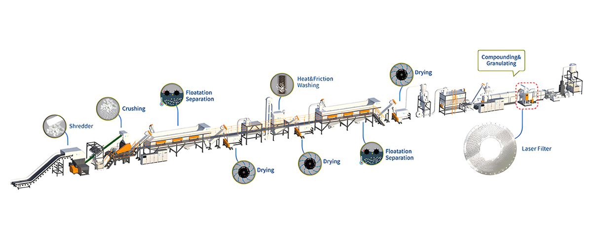
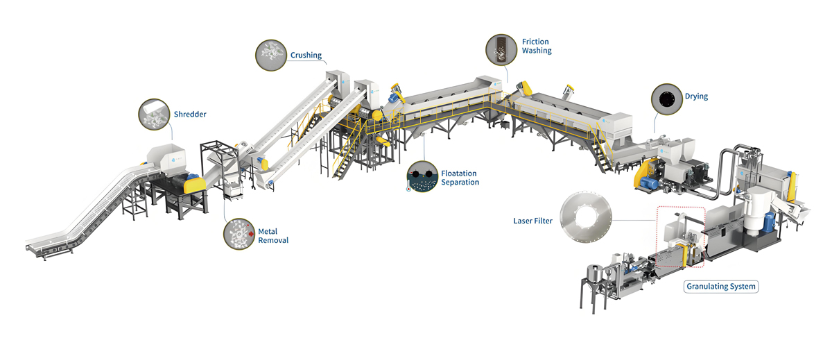
The floatation stage is not an island. Upstream friction washing and wet crushing decide how clean and how bubble-free the feed is; downstream dewatering and drying decide how much water the float fraction carries. Match water volumes across stages so the floatation tank is neither starved nor flooded. For the downstream pelletizing step, Wanplas supplies matched twin-screw pelletizing systems that accept the dewatered float fraction directly from the washing line, keeping the whole train consistent.
6.3 Heavy-medium separation for PS and PVC
Polystyrene (1.04 to 1.07) and PVC (1.35 to 1.45) both sink in plain water, so a standard floatation tank cannot split them. Dissolving salt (sodium chloride or calcium chloride) in the medium raises its density to 1.05 to 1.20 g/cm3, floating PS while PVC stays down. This works, but plan for corrosion-resistant construction and a brine wastewater treatment loop; it is a different water-management problem than the fresh-water tank this guide focuses on. Use it only when the stream genuinely mixes PS and PVC.
7. Instruments, Automation and SPC
Manual level reading is fine for commissioning, but holding separation across shifts needs instruments and a feedback loop. The good news: the water level is one of the easiest variables to close-loop control.
7.1 Level and quality instruments
Fit each tank with a level transmitter – magnetic flap, ultrasonic, or hydrostatic – with plus or minus 5 mm accuracy. Add an online turbidity meter and a periodic hydrometer or inline density meter to watch medium density, plus flow meters on make-up and return lines. Together these catch the real root causes (water quality, flow) before they show up as bad separation.
7.2 Closed-loop control
Connect the level transmitter to the PLC so make-up and overflow valves hold the setpoint automatically. The operator sets the target level from the tuned recipe; the controller compensates for evaporation, splash-out, and inflow variation. The 7-step SOP from section 3 becomes the commissioning routine that finds the recipe; automation then defends it.
7.3 SPC and records
Log level, float purity, and sink carry-over over time as statistical process control charts. A drifting average or widening spread is the early warning that feed or water quality is changing, long before a customer complaint. On Polyretec lines the same data feeds remote monitoring, so the factory’s engineers can review the trend with the operator and advise adjustments without a site visit.
7.4 Safety and environmental notes
Floatation tanks are deep water hazards. Install guard rails, anti-slip platforms, and lockout on the screws before anyone works at the open tank. For environmental compliance, run a closed water loop with settling, dissolved-air flotation, and dosing of PAC or PAM so the reuse rate reaches 85 to 95 percent; dewater the sludge and manage it as scheduled waste. The line is built to CE machinery directives, and the factory works under ISO 9001 quality management and ISO 14001 environmental management as part of the Wanplas group system.
8. Material-Specific Tuning
The four faces of section 2 are universal, but each feedstock has a personality. These are the adjustments that matter per material.
8.1 PE film and printed LDPE
Low-density polyethylene film is the most buoyant common recyclate, so it almost never sinks – the risk is the opposite: films drape over the surface, trap air, and can be dragged to the overflow still carrying labels and dirt. Keep the surface velocity at the low end (0.05 to 0.10 m/s), set the level in the upper part of the 300 to 600 mm band to give films a long calm path, and add a de-aeration spray so bubbles detach before the float paddle. Watch the discharge paddle submergence closely; film wads lift a lot of water, so keep the dip near 50 to 90 mm to protect the dewatering screen.
8.2 PET bottle flake
PET is the sink product and the false-float victim. After a friction washer, flakes carry micro-bubbles that hold them up; the level must be high enough and the surface calm enough that bubbles detach and flakes sink within the residence time. Target the mid-to-upper separation depth and confirm with the three-point sample that PET in the float outlet is under your spec. If PET keeps appearing in the float, check medium density first (SS or temperature), then nudge the level down 10 mm.
8.3 Rigid HDPE
Hard high-density polyethylene items (bottles, caps, crates) are buoyant but bulky and can trap air pockets that make them bob. Full wetting at the inlet and a steady, moderate surface current prevent them from being pushed into the sink zone by turbulence. Rigid HDPE lines usually run the float screw a touch faster than film lines because the pieces are larger and need positive conveyance, which means a slightly lower level to avoid entrainment.
8.4 Composites and multilayer materials
Multilayer films, laminates, and paper-plastic composites behave unpredictably: density varies with the layer ratio, and fragments may sink or float depending on trapped air and adhered contaminants. For these, widen the level alarm band a little, run at conservative surface velocity, and rely more on upstream sorting and a heavier wash. A single water-level setting will not rescue a stream that should have been pre-sorted; use the floatation tank to polish, not to perform miracles.
8.5 A note on the companion Polyretec film washing model
For soft PP/PE film and printed LDPE, Polyretec applies the same sink-float logic in a dedicated washing line. The Taiwan reference installation used the PTW1000 film washing model, a fully automated PP/PE film washing machine built around the level and screw principles above. Capacities for the Polyretec soft PP/PE crushing and washing line run from 500 to 1500 kg/h, and the floatation stage is tuned per the SOP in section 3 during commissioning.
| Specification | PP/PE soft washing line (500 kg/h class) | PP/PE soft washing line (1000 to 1500 kg/h class) | PTW1000 film washing model |
|---|---|---|---|
| Rated capacity (kg/h) | 500 | 1000 to 1500 | Reference film washing model |
| Feed type | Film, woven bags, agricultural film | Film, woven bags, agricultural film | PP/PE plastic film, fully automated |
| Sink-float separation | 1 tank, level tuned 300 to 500 mm | 1 to 2 tanks, level tuned 350 to 600 mm | Integrated, auto level control |
| Float screw speed (rpm) | 6 to 14 | 7 to 16 | Recipe-controlled |
| Water consumption (m3 per ton) | 0.5 to 1.0 | 0.4 to 0.8 | Closed-loop, high reuse |
| Downstream option | One-step pelletizing available | One-step pelletizing available | Links to pelletizing |
| Compliance | CE / ISO 9001 / ISO 14001 | CE / ISO 9001 / ISO 14001 | CE / ISO 9001 / ISO 14001 |
9. Polyretec Equipment, Configuration and Support
Everything in this guide is built into how Polyretec, a Wanplas factory, designs and commissions its washing lines. The sink-float separation stage is not an add-on; it is engineered from the tank geometry up, then tuned on your actual material.
9.1 Application areas
Polyretec washing and recycling equipment serves plastic product manufacturing – turning post-consumer and post-industrial waste into reusable flakes and pellets – and renewable resource utilization, reducing dependence on virgin plastic. The floatation stage sits at the heart of lines processing PET bottles, PP/PE film, woven bags, agricultural film, and rigid HDPE, all of which depend on clean density separation.
9.2 Requirement-to-configuration recommendation
Use this table to map a project brief to a Polyretec washing line configuration. Capacities follow the Polyretec washing line range; the floatation setup reflects the level principles in sections 2 through 6.
| Your requirement | Recommended Polyretec configuration | Floatation stage | Purity target |
|---|---|---|---|
| Food-grade PET bottles, 500 to 1000 kg/h | Food-grade PET bottle washing line, 500 to 1000 kg/h class | 2 sink-float tanks in series | Float purity greater than or equal to 99 percent |
| Food-grade PET, 2000 to 6000 kg/h | Food-grade PET bottle washing line, 2000 to 6000 kg/h class | 2 to 3 tanks in series | Float purity greater than or equal to 99 percent |
| PP/PE film, printed LDPE, 500 kg/h | PP/PE soft crushing and washing line, 500 kg/h class | 1 tank, upper level band | Float purity 92 to 96 percent |
| PP/PE film, 1000 to 1500 kg/h | PP/PE soft crushing and washing line, 1000 to 1500 kg/h class (PTW1000-class film washing) | 1 to 2 tanks, auto level | Float purity 92 to 96 percent, one-step pelletizing option |
| Mixed PS and PVC stream | Washing line plus heavy-medium (brine) loop | Heavy medium, density 1.05 to 1.20 | PS/PVC split greater than or equal to 95 percent |
| Post-consumer mixed rigid | Washing line with pre-sort and 2-stage floatation | Coarse plus fine tank | Float purity 95 to 98 percent |
9.3 Services and support
Polyretec backs every line with practical, field-proven support. Before shipment, the line is run on a material trial using your actual feedstock so the water level and screw setpoints are proven, not guessed. Engineers perform on-site installation and commissioning, including the 7-step level tuning from this guide. Operator training covers daily level checks, three-point sampling, and fault response from the matrix in section 5. Remote monitoring lets the factory review level and purity trends and advise without delay. The Wanplas group policy includes USD 500 free parts per year and a free replacement for damaged parts within warranty, plus an open-factory policy that welcomes customer visits at any time.
9.4 Downstream integration
After the floatation stage, the dewatered float fraction moves to pelletizing. Polyretec’s new-generation pelletizing line handles thin-walled LDPE film as well as thick-walled PE/PP regrind, and for integrated trains Wanplas supplies matched twin-screw pelletizing systems that connect directly to the washing line. The water-level discipline described here protects the quality of that feed, so the final pellet meets spec.
9.5 Project experience
Polyretec has delivered more than 100 recycling projects across 50-plus countries, with 24-plus engineer assistance resources and a credible commitment built since 2010. Reference installations include LDPE film recycling and pelletizing systems, PP non-woven and glove recycling projects, LDPE film washing with heavy-duty shredding for sticker-heavy feed, and fully automated PP/PE film washing. Each was commissioned with the same level-and-flow tuning method outlined above.
Frequently Asked Questions
What is the best water level for a sink-float separation tank?
There is no single fixed level. Set the overflow weir 60 to 75 percent of tank depth above the bottom, keep effective separation depth at 300 to 600 mm, submerge the discharge screw or paddle 50 to 120 mm, and protect a 150 to 250 mm quiescent zone at the bottom. Then tune by the 7-step single-variable method in section 3.
Why does PET flake appear in my floating fraction?
PET is denser than water, so floating PET is almost always false float caused by air bubbles attached to flake surfaces, excessive surface velocity pushing light material toward the overflow, or suspended solids raising the apparent medium density above 1.02 g/cm3. Check those three before changing the level.
Does water temperature affect floatation separation?
Yes. Heating from 20 to 45 degrees C drops water density to about 0.990 g/cm3 and cuts viscosity by roughly 40 percent, which speeds settling but narrows the density window between float and sink phases. In winter, cold water settles slowly and usually needs longer retention or mild heating to 25 to 35 degrees C.
How do I measure separation quality in the field?
Use the three-point sampling method: take 1 kg each from the float discharge, the sink discharge, and the overflow return water, dry and weigh them, then calculate float purity percent and sink carry-over percent. Repeat after each 10 mm single-variable change so you can plot the level against both curves.
Should I raise or lower the water level at full capacity?
At full rated capacity the material bed thickens, so the optimal level usually shifts down by 5 to 15 mm versus the 40 percent load setting. Always re-verify the level window at 60, 80, and 100 percent capacity before locking the setpoint.
What screw speeds should the floatation tank use?
Typical ranges are 6 to 18 rpm for the floating fraction transfer screw and 3 to 10 rpm for the sinking fraction screw. Higher speeds create turbulence and entrainment, so tune upward only as far as the material actually moves.
Can one floatation tank separate PS from PVC?
Not in plain water. PS (1.04 to 1.07) and PVC (1.35 to 1.45) both sink in water, so you need a heavy medium such as NaCl or CaCl2 brine that raises medium density to 1.05 to 1.20 g/cm3 to float PS while PVC sinks. Account for corrosion and wastewater treatment in that loop.
How does Polyretec support floatation tank commissioning?
Polyretec, a Wanplas factory, runs material trials on your actual feedstock, performs on-site level and screw tuning, delivers operator training, provides remote monitoring support, and backs the line with USD 500 free parts per year plus an open-factory visit policy.
Conclusion
The water level in a floatation tank is a small number with outsized consequences. It sets four physical functions at once – weir height, separation depth, screw submergence, and the quiescent settling zone – and it couples tightly with feed rate, screw speed, water quality, and temperature. The reliable path is not intuition but procedure: calibrate an empty tank, run a clean-water trial, feed at low load, sample at three points, trim the level 10 mm at a time, verify across the full load range, then lock the setpoint with alarms. Do that and a single sink-float tank will hold 92 to 96 percent float purity; stage two or three tanks and you reach food-grade 99 percent.
For plants planning or upgrading a washing line, Polyretec – a Wanplas factory with project experience in more than 50 countries since 2010 – designs the sink-float separation stage from the geometry up and tunes it on your real material during commissioning. Send your feedstock description and target purity, and the engineering team will recommend a configuration, invite you to the factory for a verification run, and stand behind the line with USD 500 free parts per year and full operator training. Clean separation starts with the right water level, and the right water level starts with a measured, repeatable method.