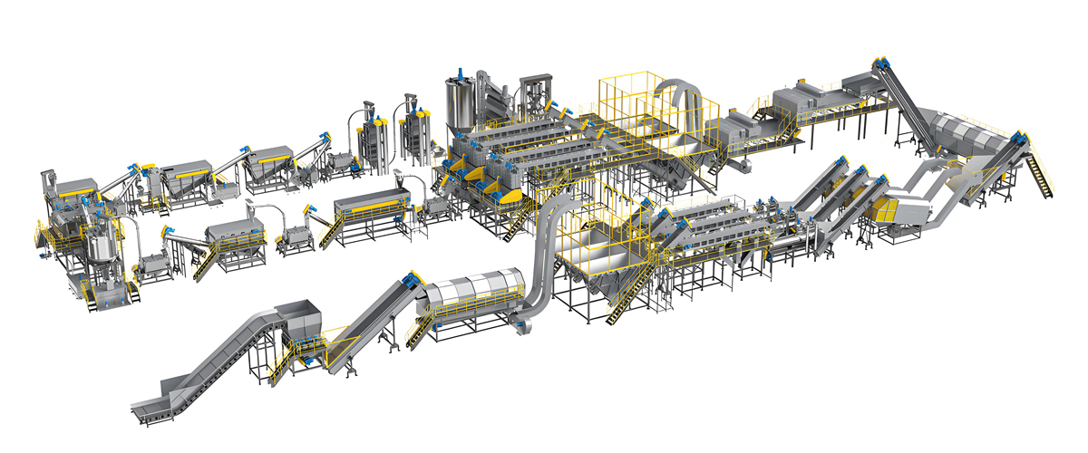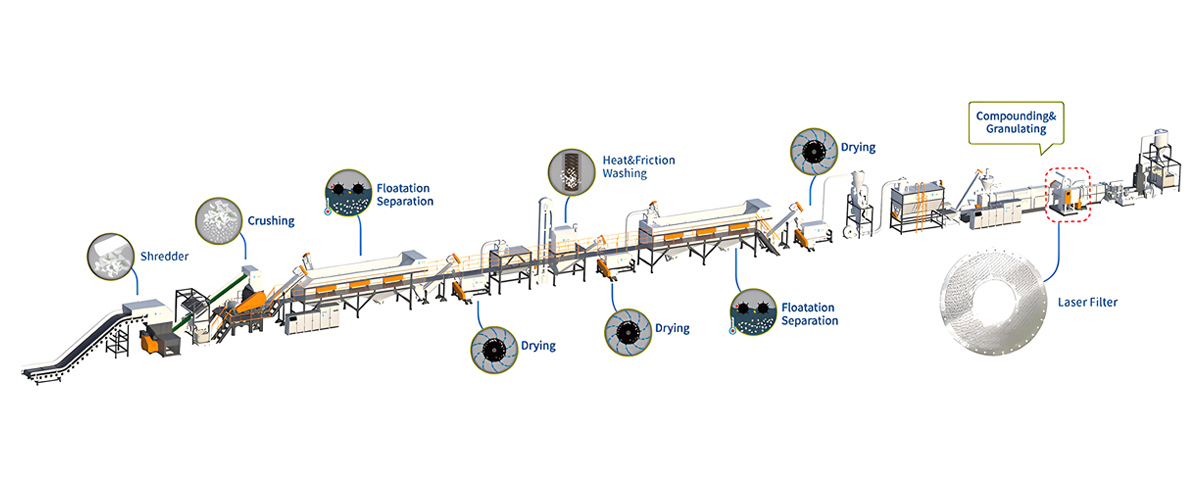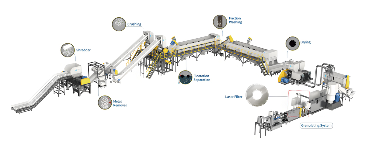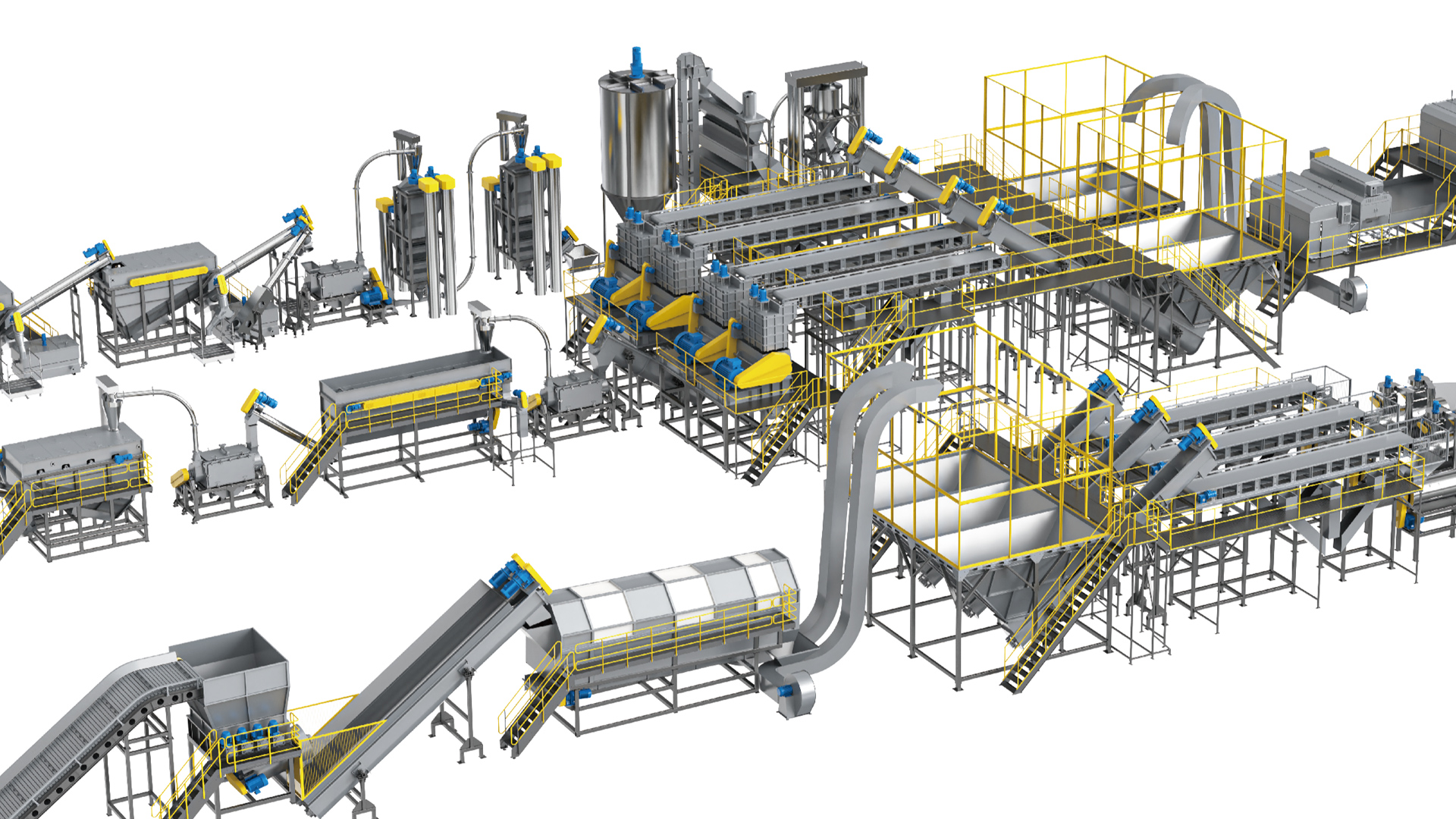

Moisture control is the single most overlooked bottleneck in a plastic recycling washing line. Operators invest heavily in washing, friction, and sorting, yet many lines lose pelletizing stability simply because the drying system behind the wash stage is treated as a passive add-on. Polyretec, a Wanplas factory specializing in plastic recycling equipment, designs the drying section as an engineered subsystem with defined targets, not a collection of rotating drums bolted onto the end of the line. This guide explains how the drying system works, what each machine demands from a maintenance program, and how to build a practical inspection and reliability routine around it.
The primary keyword for this article is “plastic recycling washing line drying system maintenance,” and the practical intent is simple: keep residual moisture within specification so the downstream pelletizing line runs without hydrolysis, bubbling, or strand breakage. Whether you run a 500 kg/h PP/PE film line or a 6000 kg/h food-grade PET washing line, the maintenance logic is consistent. Read this as a field manual, then adapt the intervals to your actual throughput, contamination level, and shift pattern.
The Role of the Drying System in a Plastic Recycling Washing Line
The drying system sits immediately after the washing, friction, and rinsing stages and immediately before storage or pelletizing. Its job is to remove the bulk of the water carried by the flakes or film so that the material can enter the extruder at a moisture level low enough to avoid thermal and mechanical defects. In a typical plastic recycling washing line, the washed material leaves the final rinse with a surface and interstitial water content in the range of fifteen to thirty-five percent by weight. That figure varies with material shape: films carry more free water than rigid flakes, and woven bags trap water in folds.
Mechanical dewatering is the first and most energy-efficient step. A centrifugal or vertical dryer removes the majority of free water, typically bringing the moisture down to single digits. Hot air drying then removes the remaining bound and clinging moisture. The combined target residual moisture depends on the polymer and the pelletizing method:
- PET bottle flakes: at or below one percent residual moisture, because PET is highly hygroscopic in the melt and sensitive to hydrolytic chain scission.
- Post-consumer film and flexible PP/PE: up to around three percent, because thin film is slow to dry and is usually processed on a squeezer before hot air.
- Hard plastics such as PP and HDPE rigid flakes: between zero point five and one percent residual moisture.
When residual moisture exceeds these ceilings, the consequences at the pelletizing stage are immediate and costly. Water trapped in the flakes flashes into steam inside the extruder barrel once the melt temperature rises above the boiling point. The steam creates bubbles in the melt, which surface as silver streaks or voids in the pellet. More seriously, the steam raises local melt pressure unevenly and weakens the extruded strand, leading to fluctuating melt pressure and, frequently, strand breakage at the die face or in the water bath. For condensation polymers such as PET and PA, the water also drives hydrolytic degradation, permanently lowering molecular weight and brittleness resistance. A drying system that drifts out of specification therefore does not merely waste energy; it degrades product quality and forces unscheduled stops.
Polyretec, as part of the Wanplas group of specialized factories, positions the drying section as a defined performance block with acceptance values, not an afterthought. The same discipline applies across its food-grade PET washing lines, soft PP/PE washing lines, and hard PP/PE washing lines. For pelletizing integration, the Wanplas group’s Kerke factory supplies co-rotating twin-screw extruders that pair with Polyretec washing systems, which makes residual moisture control a shared responsibility between the two stages.
Equipment Composition and Working Principles
A complete drying section is a sequence of machines, each with a distinct physical principle. Understanding the principle is the foundation of any maintenance plan because the failure modes map directly to the physics. The table below summarizes the core equipment and the key parameters an operator should track. Competitors in this segment such as EREMA, Starlinger, and Sorema use broadly similar unit operations, so the maintenance logic transfers across brands even when the model names differ.
| Equipment | Working Principle | Key Parameters | Typical Maintenance Focus |
|---|---|---|---|
| Centrifugal / vertical dryer | High-speed rotor throws material against a perforated screen; centrifugal force expels water through screen holes. | Rotor speed 800 to 1200 rpm; blade-to-screen gap 3 to 8 mm; screen hole 3 to 6 mm. | Bearing grease, dynamic balance, screen wear, blade wear, guards. |
| Squeezing dryer / mechanical squeezer | Screw compresses film against a slotted barrel; mechanical pressure squeezes water out through slots. | Heating zone 120 to 160 deg C; slot drainage; torque overload protection. | Screw and barrel wear, heating zones, slot blockage, seals. |
| Hot air pipeline / thermal dryer | Heated air carries moisture away from material in a duct or fluidized zone; cyclone separates fines. | Heater 30 to 120 kW; air temp 90 to 130 deg C; fan pressure matched to duct. | Heater elements, fan, duct fouling, cyclone, overheat risk. |
| Silo and dust removal | Storage buffer with baghouse dust collection and zig-zag air separation of light contaminants. | Baghouse cleaning cycle; air damper calibration. | Filter bags, damper setting, level sensors. |
| Compressed air and instruments | Pneumatics drive actuators; sensors regulate temperature, level, and residual moisture. | PT100 sensors; inverter cooling; online moisture detection. | Sensor calibration, filter drains, drive cooling. |
The order matters. Mechanical dewatering always precedes thermal drying because removing water by centrifugal force or squeezing costs a fraction of the energy required to evaporate it. A well-tuned centrifuge or squeezer reduces the load on the hot air stage, and that relationship is the central theme of the energy section later in this guide. Treat the drying section as a cascade: each machine should hand off material at the lowest achievable moisture so the next machine works less.
Centrifugal / Vertical Dryer Maintenance
The centrifugal or vertical dryer is the workhorse of the dewatering stage. A vertical shaft carries a high-speed rotor fitted with blades or paddles. Material is fed from the top or side, flung outward by centrifugal force against a perforated screen basket, and the expelled water drains through the screen holes while the dried flakes fall through an outlet. Rotor speed typically runs between 800 and 1200 rpm depending on machine size and material density. The clearance between the rotating blades and the stationary screen is a critical dimension, normally held at three to eight millimeters; too large a gap lets water ride back with the material, too small a gap risks blade-to-screen contact.
Rotor Bearings and Lubrication
The rotor assembly runs on heavy-duty bearings that absorb both radial and axial loads. Grease replenishment is normally scheduled every four hundred to eight hundred operating hours, with the exact interval set by bearing size, seal condition, and dust exposure. Over-greasing is as harmful as under-greasing because excess grease churns, heats, and can damage seals; follow the machine manual’s specified grease volume per port. Use a lithium-complex or polyurea grease rated for the operating temperature, and never mix incompatible grease families in the same bearing. A grease analysis or at least a visual inspection of spent grease color can reveal early contamination.
Dynamic Balance and Vibration
Because the rotor turns above 800 rpm, even a small mass imbalance produces large forces. The accepted vibration limit for the assembly is a velocity of four point five millimeters per second RMS. A monthly vibration reading trend is the most reliable early-warning signal for imbalance, bearing wear, or a loose impeller. When vibration climbs, stop the machine and inspect: accumulated material on the rotor, a bent shaft, a cracked blade, or worn bearings are the usual causes. Re-balancing should be done by a qualified technician using a calibrated balancing stand; field “eyeball” balancing is not acceptable for a high-speed rotor.
Screen Basket: Clogging, Wear, and Damage
The screen basket has holes of three to six millimeters. Two failure modes dominate. First, clogging: fine labels, glue, and organic slime close the holes, raising water carryover and motor load. A clogged screen is identified by rising motor current and higher residual moisture at unchanged throughput. Second, wear and tearing: abrasive contamination such as sand or glassground through the screen, enlarging holes or creating tears. Oversized holes let flakes escape with the water or let blades strike the basket. Inspect the screen at every weekly check, and keep a spare basket on hand because screen replacement is the most common unplanned downtime event in this machine.
Blade and Paddle Wear
The blades or paddles that fling the material wear on their leading edges. As they thin, the gap to the screen grows and dewatering efficiency drops. Measure blade thickness periodically and replace when wear reaches the limit set by the manufacturer, typically when the gap exceeds eight millimeters. Worn blades also change the material trajectory and can overload the motor. Replace blades as a set to preserve balance rather than mixing old and new.
Guards, Interlocks, and Access Doors
A vertical dryer is a high-speed rotating machine with a heavy lid and access doors. Every door must have a verified interlock that cuts power before the door opens. Before any internal work, apply lockout and tagout so the rotor cannot be energized. Damaged guards or bypassed interlocks are a serious safety violation and must be corrected immediately. The inspection checklist later in this guide includes interlock verification as a non-negotiable daily item.
Squeezing Dryer / Mechanical Squeezer Maintenance
For thin PP/PE film, agricultural film, and woven bags, a centrifuge alone cannot reach target residual moisture because film traps water in folds and has a huge surface area. The squeezing dryer, also called a mechanical squeezer, uses a screw to compress the material against a slotted barrel. Mechanical pressure forces free water out through the slots while the compacted “noodle” or cake of plastic exits the end. Many squeezer designs add a heating zone of 120 to 160 degrees Celsius to soften the film slightly, improve water release, and preheat the material for the pelletizing step.
Screw and Barrel Wear
The screw and the slotted barrel are the heart of the squeezer and the most wear-prone. Abrasive fillers, sand, and trapped debris accelerate wear on the screw flight tips and the barrel slots. As clearance grows, squeezing pressure drops and residual moisture rises. Monitor screw-to-barrel clearance against the rebuild limit, and plan a screw rebuild or barrel re-line on a scheduled basis rather than waiting for failure. Hard-faced or nitrided screw flights extend service life, and the extra cost is justified on contaminated feed.
Heating Zones and Temperature Control
Where the squeezer is heated, the 120 to 160 degrees Celsius range must be held zone by zone. Failed heaters, broken thermocouples, or poor contactors cause cold spots that reduce water release and hot spots that risk melting the film into a solid plug. Verify each zone’s temperature against the setpoint during the weekly check, and replace heater bands before they fail completely. A plugged squeezer from overheated film is a difficult and hazardous clearance job.
Drainage Slot Blockage
The slots through which water escapes clog with fines, label residue, and softened polymer. Blocked slots force water to stay in the material and raise the motor torque. A routine high-pressure or mechanical cleaning of the slots prevents gradual performance loss. If slots are deformed by a foreign object, they should be re-machined or the barrel section replaced.
Torque Overload Protection and Seals
The screw is driven through a gearbox with an overload device, often a shear pin or torque-limiting coupling, that protects the screw from a jam. Confirm the protection setting matches the design value and that the spare shear elements are the correct rating. The thrust bearing and shaft seals at the discharge end need lubrication and inspection; leaking seals admit water into the gearbox oil, which destroys bearings. Drain and sample the gearbox oil on the scheduled interval and watch for water ingress.
Hot Air Pipeline and Thermal Dryer Maintenance
After mechanical dewatering, the hot air stage removes the residual bound moisture. Heated air is blown through or past the material in a duct, fluidized bed, or rotary zone, carrying water vapor to exhaust while a cyclone or baghouse captures fines. Heater power ranges from 30 to 120 kW depending on line capacity, and air temperature is normally zoned between 90 and 130 degrees Celsius. The fan must deliver both the required volume and the static pressure to overcome the duct, material bed, and filtration resistance.
Heater Elements and Power Control
Electric heater banks fail gradually as individual elements open. A failing bank reduces achievable temperature and forces longer residence or higher airflow, raising energy use. Test heater continuity on the monthly schedule and replace elements in matched sets to keep the load balanced across phases. Control contactors and solid-state relays should be checked for overheating signs; a failed relay can leave a bank permanently on, causing over-temperature.
Fan, Air Volume, and Static Pressure
The circulating fan is the lungs of the system. A drop in airflow from a worn impeller, slipping belt, or clogged filter reduces drying dramatically even at correct temperature. Measure fan current and differential pressure across the duct on a trend; a creeping change signals fouling or wear. Belt-driven fans need tension and alignment checks; direct-driven fans need impeller and motor condition checks. Match fan speed to throughput using the inverter rather than running at full speed regardless of load.
Duct Fouling, Material Buildup, and Cyclone
The hot duct interior accumulates fine powder, especially from PET or rigid flakes. Buildup narrows the cross-section, raises pressure, and creates dead zones where material bakes onto the wall. A periodic internal inspection and mechanical cleaning prevents restriction. The cyclone separates fines from the airstream; its cone and dip-pipe must be clean and correctly set, or fines escape to the baghouse and raise dust load. Watch the cyclone pressure drop as a fouling indicator.
Overheat and Melt-Agglomeration Risk
Polypropylene and polyethylene have relatively low softening points. If the hot air temperature overshoots or material stagnates in a hot zone, PP/PE flakes soften, stick together, and form agglomerates that later jam the pelletizing feed or appear as black specks. Zone the temperature so the inlet is hotter and the outlet cooler, keep material moving, and never idle a heated zone with static material inside. Install independent over-temperature cutouts that trip on sensor failure, not only on setpoint exceedance.
Silo, Dust Removal, and Airflow Separation
The dried material is buffered in a silo before pelletizing or packing, and the associated dust removal protects both product quality and the workplace. A baghouse or cartridge collector captures the fine dust generated by the drying and conveying, while a zig-zag air separator can reject light contaminants such as residual film or paper by calibrated airflow.
Baghouse Cleaning Cycle
The baghouse filter bags or cartridges load with dust over time, raising differential pressure and reducing suction. A cleaning cycle, usually reverse-pulse, must be timed correctly: too frequent wastes compressed air and accelerates bag wear, too infrequent chokes the collector. Set the cleaning interval from the observed pressure trend rather than a fixed guess, and replace bags when their residual pressure at clean condition exceeds the limit or when pinholes appear. Damaged bags let fines escape and create a dust hazard downstream.
Zig-Zag Air Separator Damper Calibration
The zig-zag separator uses a vertical zig-zag duct with counter-current air to lift light fractions out while heavy flakes fall through. Its performance depends entirely on air damper setting relative to material rate. A mis-calibrated damper either drops good flakes into the reject or lets contamination pass into product. Recalibrate the damper whenever the feed grade, thickness, or rate changes, and document the setting so it can be restored. This is a lightweight but high-value maintenance task.
Silo Level and Coning
Silo level sensors, whether rotary paddles, capacitance, or radar, fail from dust coating or mechanical jam. A false full or empty signal disrupts the buffer and can starve or flood the pelletizer. Clean sensor faces on the weekly check. Watch for material “coning” or bridging above the outlet, which a vibrator or air cannon relieves; verify these aids function and are not damaging the silo wall.
Compressed Air and Instrumentation Maintenance
Pneumatic actuators, vibrators, and cleaning pulses depend on clean, dry compressed air. Instrumentation governs temperature, level, and increasingly residual moisture. This subsystem is small but its failures cause outsized disruption because it controls the larger machines.
Sensors: PT100, Moisture, and Level
Temperature sensors are typically PT100 platinum elements. They drift and should be calibrated on a scheduled basis against a reference, because a sensor reading ten degrees low can mask an under-performing dryer. Online residual-moisture detectors, where fitted, need their own calibration and sample-path cleaning; a fouled optical or capacitive cell gives false confidence. Level and pressure transmitters need impulse-line or diaphragm cleaning to avoid clogging.
Inverter Cooling and Filters
The variable frequency drives that control dryer rotors, fans, and screw feeders generate heat and rely on cooling fans and air filters. Clogged drive filters cause thermal trips exactly when the line is running hardest. Clean drive cabinet filters on the monthly schedule, verify cabinet cooling, and keep the cabinets at the rated ingress protection. A drive trip on the centrifuge fan stops the whole drying cascade.
Air Preparation and Leaks
Compressed-air preparation units (filter, regulator, lubricator) need drain checks and element replacement. Undrained filters pass water into actuators and freeze in cold climates. A leaking air system steals energy and reduces pulse pressure for the baghouse. Walk the air lines on the weekly check and tag leaks for repair.
Five-Level Preventive Maintenance Schedule
A reliable drying section runs on a structured inspection hierarchy rather than reactive repair. The table below defines daily, weekly, monthly, quarterly, and yearly tasks with the acceptance criterion, typical labor time, and the spare part involved. Adjust the intervals to your operating hours; a three-shift line compresses the calendar.
| Level | Item | Acceptance Criterion | Labor (hr) | Spare / Consumable |
|---|---|---|---|---|
| Daily | Interlock and guard verification | Door interlock cuts power on open; no bypass. | 0.2 | None |
| Daily | Residual moisture check at outlet | PET below 1 percent; film below 3 percent. | 0.2 | Moisture test kit |
| Daily | Abnormal noise and vibration listen | No metallic grinding; vibration below alarm. | 0.2 | None |
| Weekly | Screen basket inspection and clean | Holes open 3 to 6 mm; no tears. | 1.0 | Screen basket (spare) |
| Weekly | Blade gap measurement | Gap 3 to 8 mm; blade thickness in limit. | 0.5 | Blade set |
| Weekly | Air line leak and drain check | No leaks; drains clear. | 0.5 | Seals, filter element |
| Monthly | Bearing grease (centrifuge) | Fresh grease; no contamination. | 1.0 | Grease, seals |
| Monthly | Heater bank continuity test | All elements within tolerance. | 1.5 | Heater element |
| Monthly | Vibration trend recording | Velocity below 4.5 mm/s RMS. | 0.5 | None |
| Monthly | Drive cabinet filter cleaning | Filters clean; cabinet temp normal. | 0.5 | Filter element |
| Quarterly | Squeezer screw and barrel clearance | Within rebuild limit. | 3.0 | Screw, barrel liner |
| Quarterly | Baghouse bag inspection | No pinholes; pressure in range. | 2.0 | Filter bags |
| Quarterly | PT100 sensor calibration | Within plus/minus tolerance. | 1.0 | Sensor |
| Yearly | Rotor dynamic balance | Balanced to grade; vibration low. | 6.0 | Bearings, blades |
| Yearly | Gearbox oil drain and fill | No water; correct grade. | 3.0 | Oil, seals |
| Yearly | Full insulation and duct audit | No heat loss; ducts clean. | 4.0 | Insulation, gaskets |
Lubrication Chart and Predictive Maintenance
Lubrication is where most drying-section reliability is won or lost. The chart below maps each lubrication point to the grease or oil category and the interval. Keep it as a laminated card at the machine and record each application in a logbook so trends become visible.
| Lubrication Point | Lubricant Category | Interval | Note |
|---|---|---|---|
| Centrifuge rotor bearings | Lithium-complex or polyurea grease | 400 to 800 operating hours | Controlled volume; no mixing. |
| Squeezer gearbox | Industrial gear oil, specified grade | Annual drain and fill | Check for water ingress. |
| Squeezer thrust bearing | High-load grease | Quarterly | Seal integrity critical. |
| Hot air fan bearings | High-temperature grease | 800 to 1200 operating hours | Heat-rated only. |
| Conveyor and feeder bearings | General-purpose grease | Monthly | Exposed to dust. |
| Pneumatic cylinders | Micro-lube or none (non-lube type) | Per air prep schedule | Avoid over-lubrication. |
Predictive Maintenance Signals
Beyond the calendar, four signals predict failure before it happens. Vibration on the centrifuge rotor and squeezer gearbox reveals imbalance and bearing wear. Motor current on the centrifuge, squeezer, and fan reveals screen clogging, slot blockage, or duct fouling because each adds load. Bearing and oil temperature trends reveal lubrication loss long before seizure. Energy consumption per ton of dried material is the master indicator: a slow rise means something is degrading across the cascade. Record these values in a simple spreadsheet and act on trend, not just on alarm.
Common Fault Troubleshooting
The table below pairs each common drying-section fault with its typical phenomenon, root cause, corrective action, and the relative downtime you should expect. “Relative downtime” is expressed as Low, Medium, High, or Very High so it can be compared without currency. Use it to prioritize spare holding and crew training.
| Fault | Phenomenon | Root Cause | Countermeasure | Relative Downtime |
|---|---|---|---|---|
| Residual moisture above target | Outlet flakes wet; pelletizing bubbles. | Clogged screen, low rotor speed, weak heater, low airflow. | Clean or replace screen, verify speed and heater, restore airflow. | Medium |
| High centrifuge vibration | Shake, noise, rising bearing temp. | Imbalance, worn bearing, loose blade, bent shaft. | Stop, inspect, re-balance, replace bearing or blade. | High |
| Abnormal noise or knocking | Metallic sound from rotor or gearbox. | Blade-screen contact, bearing failure, foreign object. | Lock out, clear object, reset gap, replace parts. | High |
| Material discharge blockage | Backfeed, motor overload, stop. | Overfeed, wet lump, screen tear, screw jam. | Reduce feed, clear lump, repair screen or screw. | Medium |
| Frequent screen rupture | Flakes lost with water; gaps grow. | Abrasive feed, wrong hole size, blade strike. | Upgrade screen grade, set gap, pre-remove grit. | Medium |
| Unstable drying temperature | Outlet moisture fluctuates. | Failed heater, bad sensor, contactor fault. | Test heater and PT100, replace faulty parts. | Medium |
| Dust emission from collector | Visible dust, high baghouse pressure. | Hole in bag, failed pulse, damper wrong. | Replace bag, fix pulse, recalibrate damper. | Low |
| Abnormal energy consumption rise | kWh per ton climbs steadily. | Fouling, worn fan, poor dewatering upstream. | Clean duct, repair fan, improve centrifuge. | High |
Safety and Compliance in the Drying Section
The drying section combines high-speed rotation, high temperature, fine dust, and electrical power, so safety is engineered, not improvised. The following practices align with recognized occupational health and safety management principles such as ISO 45001, presented here as plain-text guidance rather than a certified procedure.
Lockout and Tagout for High-Speed Rotating Equipment
Every centrifuge, squeezer, and fan must be isolated from energy before any guard is opened. Lockout and tagout means physically locking the disconnect in the off position with a personal lock and a tag identifying the worker. Verify zero energy by attempting a start and confirming the rotor is stopped and cannot be restarted. This is mandatory for screen changes, blade work, and internal cleaning. Interlocks are a backup, not a substitute for lockout.
High-Temperature Surface Protection
Heater housings, ducts, and squeezer barrels reach temperatures that cause severe burns on contact. Insulate and guard hot surfaces, post temperature warning signs, and keep a safe clearance around access points. Use rated gloves and tools when working near hot zones, and never open a heated duct with material inside until it has cooled or been purged.
Dust Explosion Risk
Plastic dust, especially from PE and PP, is combustible when dispersed as a fine cloud. The explosibility of a dust is characterized by parameters such as the deflagration index, often denoted Kst, which indicates how violently a dust explodes once ignited. While the Kst concept is a technical measure rather than a permit, it underlines why the drying section needs explosion relief panels on the collector and ducts, grounded conveyance to prevent static ignition, and elimination of ignition sources such as sparks from metal in the feed. A magnet or metal separator ahead of the dryer reduces the risk of a spark-generating impact. Housekeeping to avoid dust layers is equally important because a layer can become a suspended cloud from a minor disturbance.
Noise Control
Centrifuges and fans are noisy. The workplace exposure limit is commonly set at a continuous level of eighty-five decibels, and the drying section should be designed and maintained to stay at or below that. Enclosures around the centrifuge, silencer fitting on the fan inlet, and hearing protection in designated zones keep operators safe. Rising noise is also a maintenance signal: a worn fan impeller or unbalanced rotor gets louder before it fails.
Electrical Ingress Protection
The washing and drying environment is wet and dusty. Motors, sensors, and cabinets should meet appropriate ingress protection ratings, commonly IP54 for splashing and IP65 for stronger jet exposure, to prevent water and dust from reaching live parts. Inspect cable glands, cabinet seals, and conduit entries on the quarterly check, and repair any breach immediately because a single water ingress can trip the line or cause a shock hazard.
Energy Consumption and Optimization
The drying section is one of the largest energy consumers on a plastic recycling washing line. Depending on line configuration and how much water the upstream wash leaves behind, the drying stage accounts for roughly twenty-five to forty percent of total line electrical consumption. Most of that is the hot air heater and the fans; mechanical dewatering is comparatively cheap. This split is the key to optimization.
The Leverage of Mechanical Dewatering
Because evaporating water needs far more energy than flinging it off mechanically, every additional percentage point of moisture removed by the centrifuge or squeezer reduces the thermal load disproportionately. A practical rule of thumb used in the field: improving mechanical dewatering by one percentage point can cut hot-air energy use by several percentage points, because the heater must no longer supply the latent heat of evaporation for that water and the fan need not carry the extra vapor. Investing in screen condition, blade gap, and squeezer pressure therefore pays back through the heater bill, not just through throughput.
Waste Heat Recovery and Insulation
Exhaust air from the hot dryer leaves warm and moist. Where layout allows, a heat exchanger can recover part of that energy to preheat incoming make-up air, lowering heater demand. More universally, repairing damaged insulation on ducts and heater housings stops heat leaking to the room instead of into the material stream. A thermal imaging check during the annual audit finds the leaks that raise energy use and operator heat stress.
Variable Frequency Drives and Airflow Matching
Running the fan and rotor at fixed maximum speed regardless of throughput wastes energy during part-load operation. Matching fan speed to the actual drying demand with a variable frequency drive, and trimming rotor speed to the material rate, reduces consumption while preserving drying quality. The inverter must be kept cool and its filters clean, as noted in the instrumentation section, or the drive itself becomes the failure point.
Maintenance-Driven Energy Losses
Most energy waste in an aging drying section is maintenance-driven: a clogged screen forces longer hot-air residence, a fouled duct raises fan pressure, a worn impeller loses efficiency, and a drifting sensor over-heats the air. The single best energy program is therefore the inspection schedule itself. Track kilowatt-hours per ton of dried output as a KPI; when it drifts up, the cause is almost always a maintenance gap somewhere in the cascade.
Spare Parts and Inventory Strategy
A drying section stops the whole line when it fails, so spare parts strategy is about protecting uptime, not minimizing inventory cost. Classify parts by criticality and lead time, then hold stock accordingly. The table below lists the key wear parts with typical life and the recommended stock level. Cost levels are given as Low, Medium, High, Very High, or Premium to avoid any specific pricing.
| Wear Part | Typical Life | Criticality | Suggested Stock | Cost Level |
|---|---|---|---|---|
| Centrifuge screen basket | 3 to 12 months by feed | Critical | 1 to 2 on hand | Medium |
| Centrifuge blades / paddles | 6 to 18 months | Critical | 1 set on hand | Medium |
| Rotor bearings | 12 to 36 months | Critical | 1 set on hand | Medium |
| Hot air heater element | 18 to 48 months | Critical | 1 bank on hand | High |
| Fan impeller | 24 to 60 months | High | 1 on hand for large lines | High |
| Squeezer screw and barrel liner | 12 to 30 months | Critical for film lines | Liner stock; plan screw rebuild | Very High |
| Baghouse filter bags | 6 to 24 months | High | One full set on hand | Low |
| Seals and gaskets | 6 to 18 months | Medium | Assortment kit | Low |
| PT100 sensors and relays | 24 to 60 months | Medium | Spares of each type | Low |
For critical parts with long supplier lead times, hold at least one on the shelf regardless of apparent life, because a single failure can idle a 6000 kg/h line. For low-cost consumables such as bags and seals, buy in volume to avoid rush orders. The Premium-cost items, such as a full squeezer screw and barrel assembly, are usually planned rebuilds rather than emergency buys, so budget them on a forecast rather than stocking complete units.
Frequently Asked Questions
What residual moisture should the drying system achieve for PET flakes?
For PET bottle flakes the target residual moisture after the combined dewatering and hot air drying stage is typically at or below one percent. Hard plastics such as PP and HDPE rigid flakes are usually brought to between zero point five and one percent, while post-consumer film and flexible PP/PE material is allowed a slightly higher ceiling of around three percent because thin film is harder to dry mechanically.
How often should the centrifugal dryer bearings be relubricated?
Grease replenishment for the main rotor bearing assembly is normally scheduled every four hundred to eight hundred operating hours, depending on the bearing size, sealing arrangement, and ambient dust load. A higher contamination environment shortens the interval, while a well-sealed and clean installation can extend it toward the upper end of the range.
Why does excess residual moisture cause strand breakage during pelletizing?
Water trapped in flakes vaporizes inside the extruder barrel when the melt temperature exceeds the boiling point. The resulting steam bubbles expand, raise local melt pressure unevenly, and weaken the extruded strand. Combined with hydrolytic chain scission of the polymer, the strand loses tensile strength and snaps at the die face or in the water bath.
What is the safe vibration limit for a vertical centrifugal dryer?
The commonly applied acceptance and alarm threshold for the rotor assembly is a vibration velocity of four point five millimeters per second RMS. Exceeding this value indicates imbalance, bearing wear, or a loose impeller and should trigger a controlled stop for inspection before damage escalates.
Can I skip the squeezer on a film recycling line?
For thin PP/PE film and woven bag material a mechanical squeezer is strongly recommended because film holds a very high water film after washing and a centrifuge alone cannot reach the required residual moisture. Running film through only a centrifuge forces the hot air dryer to remove far more water, raising energy use and risking melt agglomeration in the pelletizing step.
How do I reduce drying section energy consumption?
The most effective lever is to maximize mechanical dewatering before the hot air stage because every percentage point of water removed mechanically avoids a disproportionate amount of thermal energy later. Supporting measures include repairing insulation, matching fan speed to throughput with variable frequency drives, recovering exhaust heat, and keeping screens and cyclones clean to preserve airflow.
What causes a clogged screen basket and how do I detect it early?
Fine labels, glue, organic slime, and abrasive grit close the three to six millimeter holes over time. Early signs are a gradual rise in motor current, higher outlet residual moisture at unchanged throughput, and a drop in discharge rate. Inspect the screen weekly, keep a spare basket, and act on the current trend rather than waiting for a stoppage.
How should I manage dust explosion risk around the dryer and silo?
Plastic fines such as PE and PP dust are combustible when dispersed, and their explosibility is characterized by parameters such as the deflagration index Kst. Mitigation includes explosion relief panels on the collector and ducts, grounded conveyance to prevent static ignition, a metal separator ahead of the dryer to remove spark sources, and disciplined housekeeping so dust layers cannot become suspended clouds.
Conclusion
The drying system is not the tail end of a plastic recycling washing line; it is the gatekeeper of pelletizing quality and a major share of the line’s energy bill. A disciplined program built on the five-level inspection schedule, a clear lubrication chart, and predictive signals such as vibration, current, temperature, and energy-per-ton will keep residual moisture within specification and avoid the strand breaks, bubbling, and melt-pressure swings that ruin recycled pellet. Polyretec, a Wanplas factory, designs its washing lines so the drying block has defined acceptance values, and the same maintenance discipline applies across PET, rigid PP/PE, and film lines. For operations that integrate washing with pelletizing, the Wanplas group’s Kerke factory supplies twin-screw extruders that pair with Polyretec drying output, making moisture control a shared engineering target. Start by benchmarking your outlet moisture today, then close the gaps in screen condition, bearing lubrication, heater integrity, and dust control one level at a time.