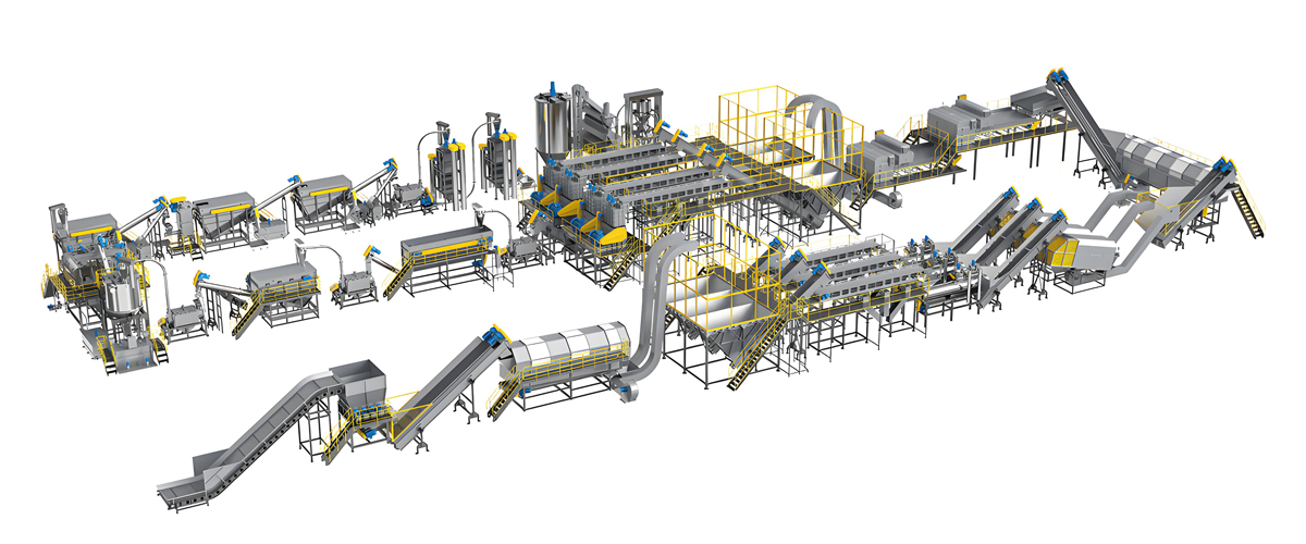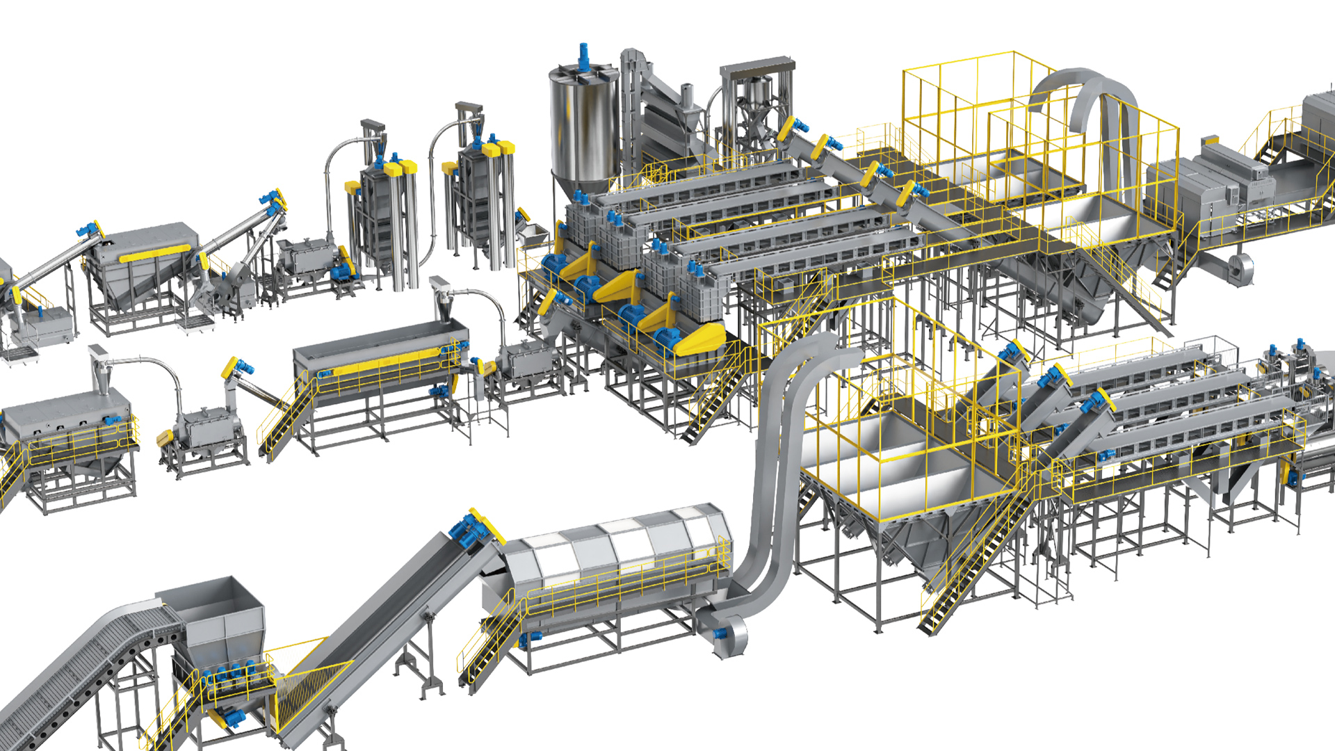

Building a plastic recycling factory from an empty industrial shed is not a purchasing exercise. It is a process engineering project in which the crusher, the friction washer, the float-sink tank, the hot washer, the dewatering centrifuge and the pelletizing unit must all agree on the same mass balance, the same water balance and the same contamination budget. An Austrian tech plastic recycling line — meaning the Central European process route that prioritizes mechanical separation intensity, tightly closed water loops and gentle thermal history over brute-force throughput — has become the reference architecture for investors who need consistent, sellable recyclate rather than simply “washed plastic”. This guide explains how that route is engineered, configured, delivered and commissioned as a genuine turnkey factory setup, from feedstock characterization through to a signed capacity acceptance certificate.
Polyretec, a Wanplas factory, has been engineering crushing, washing and pelletizing systems since 2010, with the brand formally established in 2017. The team has delivered more than 100 project references and provides globalization services across 50-plus countries, supported by 24-plus engineers who handle process design, installation and commissioning. The design language combines the Austrian-origin process route with Chinese manufacturing depth, which is exactly why a complete washing line can be specified to European separation standards while remaining commercially realistic for a first-time recycler in Southeast Asia, Latin America or the Middle East. Throughout 2026 the questions arriving at our engineering desk have shifted from “what does a washing machine cost” to “what does a factory that reliably produces food-contact-grade flakes actually look like” — and that is the question this article answers.
What follows is deliberately practical. You will find the true scope boundary of a turnkey contract, a comparison of turnkey versus piecemeal procurement expressed in risk levels and schedule months, four feedstock-specific process routes with their equipment differences, a ten-stage walkthrough of the line with real process windows, two Polyretec product blocks with specification tables, a requirement-to-configuration selection table, the water and utility engineering that most first-time buyers underestimate, a month-by-month delivery schedule, and the acceptance criteria that determine whether your ramp-up ends in a signature or an argument.
What “Turnkey” Really Means in a Plastic Recycling Line Project
A genuine turnkey plastic recycling line contract transfers integration responsibility to a single engineering party, so the customer buys a guaranteed output quality at a guaranteed throughput rather than a list of machines. The distinction matters because roughly half of the technical problems in a recycling plant occur at interfaces — between the crusher discharge and the washer inlet, between the dewatering centrifuge and the thermal dryer, between the water treatment skid and the process tanks — and interfaces belong to whoever owns the integration.
In Polyretec practice the turnkey boundary is defined before any drawing is issued. The scope begins with feedstock characterization: a physical sample is required, and the engineering team records bulk density, moisture, ash and dirt fraction, label and adhesive type, polymer mix, metal content and the proportion of oversize or non-plastic items. From that sample a mass balance is built, and every downstream machine is sized from the mass balance rather than from a nominal nameplate figure. This is the single most important discipline in the Austrian tech route: the line is dimensioned for the worst feedstock the customer will realistically receive, not the cleanest.
Scope Boundary of a Complete Turnkey Delivery
The table below sets out what a full turnkey package includes and, just as importantly, what remains a local responsibility. Clear ownership of each item at contract stage prevents the classic six-week delay in which nobody has poured the equipment foundations because everyone assumed somebody else would.
| Work Package | Included in Turnkey Supply | Customer / Local Scope | Typical Interface Document |
|---|---|---|---|
| Feedstock study and mass balance | Sample testing, yield calculation, contamination budget | Representative sample supply, supplier contracts | Process data sheet |
| Process and equipment design | P&I diagram, equipment list, motor list, layout | Site survey data, building drawings | General arrangement drawing |
| Equipment manufacture and testing | Fabrication, assembly, no-load and load testing | Witness inspection if requested | Factory test report |
| Packing and shipping | Export packing, container loading plan, documents | Import clearance, inland haulage, unloading crane | Packing list and loading diagram |
| Civil works and foundations | Foundation load and anchor drawings | Concrete, drainage trenches, pits, building works | Civil interface drawing |
| Mechanical and electrical installation | Supervision engineers, alignment, control cabinet | Local labor, cable trays, main incoming power | Installation manual |
| Commissioning and trial production | Single-machine, interlocked and loaded commissioning | Feedstock for trials, utilities, operators | Commissioning protocol |
| Training and handover | Operator, maintenance and quality-control training | Nominated trainee team, shift roster | Training record and acceptance certificate |
Turnkey Versus Piecemeal Procurement: An Honest Risk Comparison
Buying machines individually from several sources looks attractive on a spreadsheet and frequently is a false economy, because integration risk is simply transferred to the buyer’s own team. The comparison below expresses the difference in risk level, schedule months and integration effort rather than in commercial terms, since the technical consequences are what determine whether the plant reaches nameplate capacity.
| Evaluation Dimension | Single-Source Turnkey Line | Piecemeal Multi-Vendor Purchase |
|---|---|---|
| Process integration risk | Low — one mass balance governs all stages | High — each vendor sizes to its own assumption |
| Mechanical interface risk | Low — matched chute, conveyor and flange design | High — on-site fabrication usually needed |
| Electrical and control integration | Low — one central control system, full interlocking | High — separate panels, manual start sequences |
| Water balance and treatment sizing | Low — treatment sized against real stage-by-stage load | High — treatment often undersized after the fact |
| Design to shipment schedule | Approximately 4 to 6 months | Approximately 5 to 9 months, gated by slowest vendor |
| Installation to stable output | Approximately 2 to 3 months | Approximately 4 to 8 months |
| Responsibility when output quality fails | Single accountable party | Disputed between suppliers |
| Spare parts management | Low complexity — one consolidated parts list | Medium to High — multiple part standards |
| Suitability for first-time recyclers | Recommended | Only viable with an experienced in-house process team |
The Austrian Tech Process Route: Design Philosophy Behind the Line
The Austrian tech label in this context describes a Central European engineering philosophy rather than any particular supplier: separate mechanically before you separate thermally, keep residence time long enough for chemistry to work, and close the water loop so that cleaning intensity is not limited by water availability. Polyretec has adopted this route and adapted it to the feedstock realities of emerging markets, where input material is dirtier, more variable and more heavily labeled than typical European post-consumer streams.
Three principles define the route in practice. The first is separation redundancy. Rather than relying on a single high-performance separation step, the line applies several complementary mechanisms in series — size classification by screen, density separation in water, friction and shear at flake surfaces, air classification for light fractions, and where required electrostatic or optical sorting. Each mechanism removes a different contaminant family, so the failure of one stage degrades quality gradually instead of catastrophically.
The second principle is controlled thermal history. Every heating step imposes a cost on polymer properties, most visibly on PET intrinsic viscosity and on the melt flow rate of polyolefins. The Austrian-origin route therefore uses the hot washer to do chemical work at 80 to 95 degrees Celsius with alkaline detergent, and then removes water mechanically before applying thermal drying, so the dryer only has to remove residual surface moisture instead of bulk water. The result is a shorter, cooler drying stage and a measurably better retained property profile in the recyclate.
The third principle is water discipline. Water is the working medium of the entire washing line, and in the Austrian tech configuration it is treated as a circulating utility with defined quality targets at each stage. Dirty water from wet crushing and pre-washing never enters the final rinse; clean rinse overflow cascades backward into earlier stages. This countercurrent arrangement is the reason a well-designed line can deliver very low residual turbidity in the last rinse while consuming only a modest quantity of fresh makeup water.
Key engineering figures for a well-configured washing line: Process water recirculation typically 85 to 95 percent; fresh makeup water approximately 2 to 4 cubic meters per ton for rigid PET and 3 to 6 cubic meters per ton for heavily soiled film; hot wash window 80 to 95 degrees Celsius with 1 to 3 percent alkaline solution; centrifuge discharge moisture typically 1 to 3 percent; thermal dryer outlet moisture below 0.5 percent for pelletizing feed. All values are indicative and confirmed against the customer’s own feedstock during process design.
Four Feedstock Routes and How Their Equipment Trains Differ
There is no universal plastic recycling line, because feedstock geometry and contamination determine equipment selection more than polymer chemistry does. A PET bottle bale, a crate of rigid PE regrind, a bundle of agricultural film and a mixed post-consumer stream require four visibly different equipment trains even though all four are described as “washing lines”. The comparison below sets out the core differences that drive both layout and installed power.
| Process Element | PET Bottle Flake Route | Rigid PE / PP Route | Agricultural / Packaging Film Route | Mixed Heavily Soiled Route |
|---|---|---|---|---|
| Intake and pre-treatment | Bale opener, manual sorting belt, metal detection, trommel | Belt feed, magnetic separator, coarse pre-screen | Bale breaker, heavy-duty shredder, pre-washing drum | Shredder plus intensive pre-wash and grit removal |
| Size reduction | Wet crusher, screen 12 to 16 mm | Wet or dry crusher, screen 12 to 20 mm | Shredder then wet crusher, screen 20 to 40 mm | Two-stage shredding then wet crushing |
| Primary cleaning | High-speed friction washer, 2 to 3 units | Friction washer, 1 to 2 units | Friction washer, 3 to 4 units in series | Friction washer, 4 or more with intermediate settling |
| Density separation | Float-sink; PET sinks, PE/PP caps float | Float-sink; PE/PP float, PET/PVC/metal sink | Float-sink with long residence, sand and grit sink | Multi-stage float-sink plus hydrocyclone option |
| Hot washing | Essential — removes glue, labels, oils, 85 to 95 degrees Celsius | Optional — used when oil or print contamination is present | Essential — removes soil binder and agrochemical residue | Essential, often two hot stages |
| Dewatering and drying | Horizontal centrifuge plus hot air pipe dryer | Centrifuge plus optional thermal dryer | Squeezer or centrifuge plus thermal dryer or direct squeezing extruder | Centrifuge plus extended thermal drying |
| Typical downstream | Flake sale, or pelletizing with melt filtration | Regrind sale or pelletizing line | Agglomerator plus pelletizing, or direct film pelletizing | Pelletizing with high-efficiency melt filtration |
| Relative installed power | Medium | Low to Medium | High per ton, due to low bulk density | High |
Two observations follow from this table. First, film lines consume disproportionately more energy and floor space per ton than rigid lines because low bulk density means every machine must handle a large volume for a small mass. Second, the mixed heavily soiled route is not simply a film line with extra stages — it needs settling capacity between friction washers so that liberated grit leaves the circuit instead of recirculating and abrading equipment. Buyers who intend to process mixed municipal-origin waste should budget floor area and water treatment capacity accordingly at the design stage, not after the building is finished.
Stage-by-Stage Walkthrough of the Complete Recycling Line
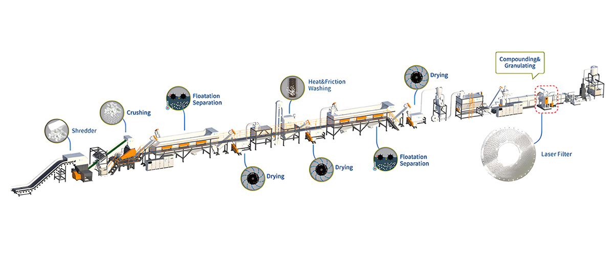
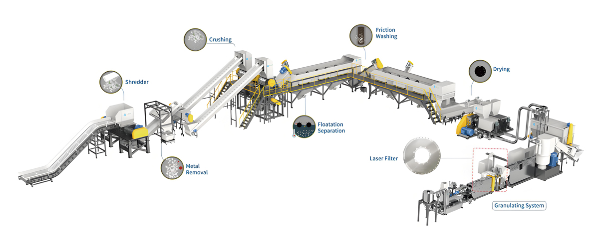
A complete crushing, washing and pelletizing line consists of ten functional stages, each with a defined process window and a defined quality checkpoint. Understanding what each stage is responsible for makes plant operation far more systematic, because when a quality deviation appears at the end of the line it can be traced backward to the stage that actually caused it.
Stage 1: Intake, Debaling and Pre-Sorting
The line begins where the truck unloads. Bales are broken by a debaler or bale opener and metered onto an inclined belt conveyor with adjustable speed, because the entire downstream line runs on a mass flow that must be steady. A manual sorting platform follows, where operators remove obvious rejects — non-target polymers, textiles, wood, large metal items and hazardous containers. An overband magnetic separator captures ferrous metal, and an eddy current or metal detection unit protects the crusher from non-ferrous fragments. A rotary trommel screen removes loose sand, stones and fines before crushing. This stage is unglamorous and decisive: contamination removed dry here never has to be removed wet later, and a single missed metal fragment can destroy a full set of crusher blades.
Stage 2: Wet Crushing and Size Reduction
The wet crusher reduces the material to flakes while water is injected into the cutting chamber. Wet crushing serves three purposes simultaneously: it suppresses dust, it begins the washing action at the moment of maximum surface generation, and it cools the blades so that heat-sensitive polymers do not smear. Rotor and stator blade geometry is selected for the feedstock — a scissor-cut arrangement for tough rigid material, a straight-cut arrangement for brittle streams. Blade material is typically a high-alloy tool steel, heat treated for a hardness that balances edge retention against chipping resistance, and blades are designed to be reground several times before replacement.
Screen aperture is the master variable for flake size. For PET bottle flake production a 12 to 16 millimeter screen is standard, since finer flakes wash better and dry faster but generate more fines and reduce bulk density. For rigid PE and PP regrind a 12 to 20 millimeter screen is common. For film a coarser 20 to 40 millimeter aperture avoids excessive fines and reduces load on the friction washers. The crusher must be sized with meaningful headroom above nominal throughput, because feed density varies and a crusher running at its limit becomes the bottleneck for the entire factory.
Stage 3: High-Speed Friction Washing
The friction washer is the workhorse of surface cleaning. Flakes are propelled by a high-speed paddle rotor inside a perforated barrel while water counterflows, so that flakes rub against each other and against the perforated screen. Mud, sand, label fragments and softened adhesive are stripped from the surface and pass through the perforations with the dirty water. Rotor speed, paddle pitch and the number of units in series are tuned for the contamination level: two units are typical for reasonably clean PET bales, three or four for agricultural film carrying heavy soil load. Friction washers are also where residence time can be traded against intensity, and the Austrian tech route tends to prefer more units at moderate intensity over fewer units at aggressive intensity, because aggressive friction generates fines and fines depress yield.
Stage 4: Float-Sink Density Separation
Float-sink separation exploits the density gap between polymer families in plain water. Polyethylene sits at roughly 0.91 to 0.96 grams per cubic centimeter and polypropylene at roughly 0.90 to 0.91, both below water at 1.0, so they float. PET at roughly 1.33 to 1.40 and PVC at roughly 1.30 to 1.45 sink, as do metal fragments, sand and stones. A float-sink tank therefore performs the single most valuable separation in the whole line at almost no energy cost.
Engineering quality shows in the details: tank length must give sufficient residence time for slow-rising film flakes, paddle agitators must break up floating mats without re-entraining sinkers, a bottom screw conveyor must continuously evacuate the sink fraction so it does not accumulate, and surface skimming must be steady rather than intermittent. Because PET and PVC both sink, float-sink alone cannot separate them, which is why PVC control in PET lines depends on upstream manual sorting plus downstream optical or sorting technology. This is the origin of the strict PVC limits that flake buyers apply.
Stage 5: Hot Washing with Alkaline Detergent
The hot washer is where chemistry replaces mechanics. Flakes are held in a heated, agitated vessel containing an alkaline solution, typically 1 to 3 percent caustic with a surfactant and defoamer package, at 80 to 95 degrees Celsius, with residence time in the range of 10 to 20 minutes. The combination saponifies oils and greases, hydrolyzes the adhesive layer that bonds labels to bottles, and detaches residual glue and printing ink. For food-contact-grade PET flake production this stage is mandatory, and its temperature and concentration must be controlled closed-loop rather than set manually, because both drift as the process runs.
Heating is normally provided by steam injection or by a heat exchanger fed from a steam boiler or thermal oil heater. Steam consumption is a significant operating item, so heat recovery from hot wash overflow into incoming rinse water is a standard feature in a well-engineered line. Vessel material must be stainless steel of an appropriate grade, since hot alkaline solution attacks carbon steel rapidly.
Stage 6: Multi-Stage Rinsing and Turbidity Control
After hot washing, the flakes carry alkaline solution and dissolved contamination that must be removed before drying. Rinsing is arranged as two or three stages in countercurrent, so the cleanest water contacts the cleanest flakes. Rinse quality is monitored by turbidity, and the practical target for the final rinse in a food-grade PET line is a low single-digit turbidity reading, with pH returned close to neutral. Where the finished flake is destined for high-specification applications, the final rinse may use demineralized water to avoid depositing mineral residue on the flake surface as it dries. Turbidity trending is one of the most useful operational indicators available: a rising final rinse turbidity almost always signals that an upstream friction washer or the water treatment system is losing performance.
Stage 7: Mechanical Dewatering
A horizontal centrifugal dewatering machine spins water out of the flake stream, reducing residual moisture from a saturated condition to typically 1 to 3 percent. Mechanical dewatering is far more energy-efficient than thermal drying — removing a kilogram of water by centrifuge costs a small fraction of what it costs by hot air — so the design intent is always to push the centrifuge as hard as practical and let the dryer handle only the remainder. Screen basket aperture, rotor speed and the wear condition of the rotor blades determine performance, and a worn centrifuge is one of the most common hidden causes of high dryer energy consumption in an operating plant.
Stage 8: Thermal Drying
A hot air pipe dryer, sometimes combined with a fluidized bed or infrared unit, carries flakes through a heated air stream to bring moisture below 0.5 percent, and below 0.3 percent where the flake feeds directly into a pelletizing extruder without a dedicated crystallizing dryer. Air temperature must be limited to avoid softening or agglomerating the flake — for PET flakes the practical window sits well below the crystallization-driven sticking point, while for PE and PP film the window is narrower still. A cyclone separates dried flakes from the air stream and a zigzag air classifier can be integrated at this point to remove residual light fractions.
Stage 9: Label, Fines and Foreign Particle Removal
Even after washing, a fraction of label material and light film remains entrained. Air classification, usually a zigzag separator, exploits the difference in terminal velocity between compact flakes and light label fragments. Fines are removed by a vibrating screen. Where the target specification requires it, electrostatic separation can remove residual PVC or paper, and optical sorting can remove off-color flakes and residual foreign polymers. Polyretec integrates these units as options within the line control system rather than as standalone islands, so that reject streams are conveyed automatically and the operator sees rejection rates on the same panel as throughput.
Stage 10: Pelletizing and Melt Purification
Where the business plan calls for pellets rather than flakes, the washed and dried material feeds a pelletizing line. The extruder plasticizes the material in a heated barrel, degasses volatiles through vacuum vents, and pushes the melt through a filtration system before the pelletizer. Melt purification is the final quality gate: a continuous screen changer or a laser filter removes residual solid contamination down to fine micron levels, protecting both the pellet quality and any downstream product made from it. For downstream pelletizing, Wanplas supplies matched twin-screw systems that integrate with Polyretec washing lines, so that the extruder throughput, the dryer capacity and the washing line output are dimensioned as one system. The detailed operation and long-term maintenance of melt filtration is a subject in its own right and is not expanded here; for turnkey planning purposes what matters is that filtration capacity and screen changeover strategy are fixed during process design, because they influence extruder pressure, melt temperature and therefore polymer degradation.
Polyretec Line Configurations and Technical Specifications
Polyretec builds two principal washing line families plus matching pelletizing systems, and every project is a configuration of these families rather than a bespoke one-off design. Standardizing on proven modules is what keeps delivery schedules predictable and spare parts available, while the configuration layer allows each line to match a specific feedstock and output target.
Product Block 1: Food Grade PET Bottle Washing Line
The Food Grade PET Bottle Washing Line covers 500 kg/h to 6000 kg/h and is designed to produce flakes at several defined grades, from general fiber-grade material through to high-specification flake suitable for food-contact applications after appropriate downstream processing and approval. The line integrates debaling, sorting, metal detection, wet crushing, multi-stage friction washing, float-sink separation, hot alkaline washing, countercurrent rinsing, centrifugal dewatering, thermal drying and air classification, with the water treatment package sized as part of the same design.
| Configuration | Throughput (kg/h) | Indicative Installed Power (kW) | Fresh Water Makeup (m³/h) | Indicative Footprint (m²) | Suitable Feedstock |
|---|---|---|---|---|---|
| PET entry configuration | 500 | 160 – 220 | 1.5 – 2.5 | 350 – 450 | Sorted PET bottles, low label load |
| PET standard configuration | 1000 | 260 – 340 | 2.5 – 4.0 | 500 – 650 | Mixed-color PET bottles with labels and caps |
| PET mid-capacity configuration | 2000 | 450 – 600 | 4.5 – 7.0 | 850 – 1100 | Post-consumer PET bales, mixed sources |
| PET high-capacity configuration | 3000 | 650 – 850 | 6.5 – 10.0 | 1200 – 1500 | Municipal collection PET, high label content |
| PET industrial configuration | 6000 | 1200 – 1600 | 12.0 – 18.0 | 1900 – 2400 | Large-scale post-consumer PET, food-grade target |
Power and water figures above are indicative for planning and are confirmed in the project process data sheet once the customer’s feedstock is characterized. Footprint assumes a single-level layout with the water treatment package located adjacent to the line; a two-level arrangement with elevated tanks reduces the ground-floor area but requires greater clear height.
Product Block 2: PP/PE Soft Plastic Crushing and Washing Line
The PP/PE Soft Plastic Crushing and Washing Line covers 500 kg/h to 1500 kg/h and is designed for film, woven bags and agricultural film — the feedstocks with the lowest bulk density and highest dirt load in the industry. Agricultural film in particular can arrive carrying soil at a substantial fraction of total weight, so the line front end is built around heavy-duty shredding, pre-washing and multi-stage friction washing with settling capacity between stages. A one-step configuration that couples washing directly to pelletizing is available where the customer’s business plan targets pellets rather than washed film. The PTW1000 fully automated PP and PE film washing configuration is a representative example of this family, delivered as a complete automated line.
| Configuration | Throughput (kg/h) | Indicative Installed Power (kW) | Fresh Water Makeup (m³/h) | Indicative Footprint (m²) | Suitable Feedstock |
|---|---|---|---|---|---|
| Film entry configuration | 500 | 180 – 250 | 2.0 – 3.5 | 380 – 480 | Industrial LDPE film, clean packaging film |
| Film standard configuration (PTW1000 class) | 1000 | 300 – 420 | 3.5 – 6.0 | 600 – 780 | PP and PE film, woven bags, printed film |
| Film heavy-duty configuration | 1500 | 450 – 600 | 5.0 – 9.0 | 850 – 1050 | Agricultural film with high soil load, mixed film |
| Hard PP/PE crushing and washing line | 500 – 2000 | 150 – 550 | 1.5 – 6.0 | 320 – 950 | Crates, drums, bottles, pipes, rigid regrind |
| New Generation Pelletizing Line | 300 – 1500 | 180 – 700 | Cooling circuit only | 250 – 700 | Thin-wall LDPE film, thick-wall PE/PP regrind |
The New Generation Pelletizing Line deserves separate mention because it handles the two extremes of the polyolefin recycling world in one robust construction: thin-walled LDPE film, which is difficult to feed and easy to degrade, and thick-walled PE or PP regrind, which is easy to feed and demands high melting energy. Its design intent is maximum performance on post-consumer waste rather than on clean industrial scrap, which is the correct priority for a factory whose feedstock supply will inevitably become more contaminated as local collection expands.
Application Industries and the End Products They Feed
A recycling line only earns its return when its output has a confirmed buyer, so line configuration must be driven backward from the end product specification. Polyretec lines serve two broad application areas — plastic product production, where waste plastics are converted into reusable pellets or blocks for new products, and renewable resource utilization, where recyclate reduces dependence on primary plastic resources. In practice these translate into a handful of concrete end-product markets.
Recycled PET flake for fiber and sheet. Washed, dried and classified PET flake is the feedstock for polyester staple fiber, filament, strapping tape and thermoformed sheet. Fiber producers care most about intrinsic viscosity consistency, moisture, PVC content and fines. Sheet producers add color consistency to the list because sheet defects are highly visible. A well-run 2000 kg/h line feeding a regional fiber plant is one of the most stable business models in mechanical recycling.
Food-contact-grade rPET. Where the target is bottle-to-bottle, the washing line is only the first half of the chain: flake must go through a decontamination and solid-state polycondensation process and the whole chain must be approved under the relevant food-contact framework, whether that is an EU regulation route, an FDA no-objection route or a national equivalent such as the GB series in China. The washing line’s contribution is measured by residual PVC in parts per million, residual metal, residual adhesive and flake color consistency, all of which are set by the hot washer, the sorting stages and the rinse train.
Recycled PE film pellets. Washed agricultural and packaging film is pelletized into LDPE and LLDPE recyclate used for refuse sacks, construction sheeting, agricultural mulch film, protective packaging and drip irrigation pipe. Buyers judge these pellets by melt flow rate consistency, gel count, black speck count and odor. Odor is often the deciding factor, and odor performance traces directly to hot wash effectiveness and extruder degassing.
Recycled PP for bulk bags, crates and industrial parts. Washed PP from woven bags, crates and automotive parts becomes recyclate for FIBC bulk bag tapes, transport crates, pallets, garden furniture, pipe fittings and non-appearance automotive components. Here impact strength retention and filler consistency matter more than color.
Recycled engineering polymers. Where the incoming stream includes ABS, PC or PA, an additional density and sorting stage is required because these polymers overlap in density with PET and PVC. The recyclate serves electrical housings, appliance components and industrial parts. Engineering polymer recycling is technically demanding and usually only viable where the feedstock is a controlled industrial stream rather than a municipal one.
Selection Guide: Matching Feedstock and Output to a Configuration
The selection table below maps common project briefs to a recommended Polyretec configuration. It is a starting point for discussion rather than a substitute for a mass balance, but it will get most projects into the right capacity band and the right equipment family on the first pass.
| Feedstock Type | Target Throughput | Intended End Product | Recommended Polyretec Configuration | Key Add-On Modules |
|---|---|---|---|---|
| Sorted clear PET bottles | 500 – 1000 kg/h | Fiber-grade flake | Food Grade PET Bottle Washing Line, entry or standard configuration | Zigzag air classifier, fines screen |
| Mixed-color post-consumer PET bales | 2000 – 3000 kg/h | Sheet-grade and strapping-grade flake | Food Grade PET Bottle Washing Line, mid or high-capacity configuration | Optical sorting, electrostatic PVC removal |
| Municipal PET, food-contact target | 3000 – 6000 kg/h | Food-grade rPET flake for downstream upgrading | Food Grade PET Bottle Washing Line, industrial configuration | Dual hot wash, demineralized final rinse, full optical sorting |
| Clean industrial LDPE film | 500 kg/h | LDPE pellets for sacks and sheeting | PP/PE Soft Plastic Line, entry configuration with one-step pelletizing | Squeezing dryer, melt filtration |
| Printed PP and PE film, woven bags | 1000 kg/h | Washed film and PE/PP pellets | PP/PE Soft Plastic Line, PTW1000 class configuration | Extra friction washer, hot washer, deinking option |
| Agricultural film with heavy soil | 1000 – 1500 kg/h | LDPE pellets for mulch film and pipe | PP/PE Soft Plastic Line, heavy-duty configuration | Heavy-duty shredder, beater pre-wash, grit settling tanks |
| Rigid HDPE crates, drums, pipes | 1000 – 2000 kg/h | Regrind and HDPE pellets | Hard PP/PE Crushing and Washing Line | Metal detection, float-sink, optional hot wash |
| Washed rigid flakes from third-party washing | 500 – 1500 kg/h | Consistent pellets for injection and extrusion | Rigid Flakes Recycling and Pelletizing Line | Vacuum degassing, high-efficiency melt filtration |
| Thin-wall LDPE and thick-wall PE/PP mix | 300 – 1500 kg/h | General-purpose recycled polyolefin pellets | New Generation Pelletizing Line | Agglomerator, side feeder, twin-screw system supplied by Wanplas |
Water Circuit, Sludge Handling and Environmental Compliance
Water engineering is where recycling projects most often fail their environmental permit, and it is the part of the plant that first-time buyers most consistently underestimate. A washing line without a properly sized water treatment package is not a recycling plant; it is a pollution source with a conveyor attached.
The circuit begins with segregation. Water from wet crushing, pre-washing and the first friction washers carries the heaviest solid load and is routed to primary treatment. Water from hot washing carries alkalinity, dissolved organics and surfactant. Water from the final rinses is comparatively clean and is cascaded backward to earlier stages instead of being discharged. Keeping these three streams separate is what allows the treatment plant to be sized economically, because treating a small heavily loaded stream is far cheaper than treating a large lightly loaded one.
Primary treatment normally comprises coarse screening, grit removal and a settling stage, often assisted by a dissolved air flotation unit for the fine suspended solids that will not settle. Chemical dosing with coagulant and flocculant follows, and the resulting sludge is thickened and dewatered by filter press or screw press to a cake with a solids content typically in the range of 25 to 40 percent, which is then handled as solid waste according to local regulation. The clarified water passes through sand and fine filtration and returns to the process tanks. Alkaline hot wash effluent is neutralized before it joins the main circuit. A biological stage or activated carbon polishing step is added where the discharge permit requires a low chemical oxygen demand in the small bleed stream that must inevitably leave the circuit to prevent salt buildup.
With this arrangement, recirculation rates of 85 to 95 percent are routinely achieved, and the plant’s discharge is limited to a controlled bleed plus the moisture leaving with the sludge cake and the product. Compliance reporting is normally framed against the national discharge standard applicable at the site, with parameters such as chemical oxygen demand, suspended solids, pH and, where relevant, surfactant content monitored on a defined schedule. Polyretec provides the water balance, the treatment package specification and the expected effluent characteristics as part of the process design so that the customer’s environmental consultant can prepare the permit application from real numbers rather than assumptions.
Two further environmental items belong in the design from day one. Odor control matters wherever post-consumer feedstock is stored, because decomposing organic residue in bottles and film generates complaints faster than any other aspect of a recycling plant; enclosed storage with negative-pressure extraction and a biofilter or scrubber solves it. Noise control matters because shredders, crushers and centrifuges are the loudest machines on site; acoustic enclosures and correct foundation isolation keep boundary noise within typical municipal limits.
Automation, Interlocking and Digital Production Monitoring
A modern recycling line is controlled as one machine, not as thirty machines standing in a row. The central control system runs a defined start sequence from the end of the line backward, so that no stage ever receives material before the stage downstream of it is running, and a defined stop sequence that empties the line in the correct order to prevent material sitting in a wet machine overnight.
Interlocking is the safety and reliability backbone. Level sensors in surge hoppers modulate upstream feed rate. Motor current on the crusher is used as a load feedback signal to the intake conveyor, so the crusher self-regulates rather than choking. Blockage detection on chutes triggers automatic feed stoppage. Temperature and level control loops manage the hot washer. Pump and valve status is confirmed before any tank is filled. Emergency stop circuits are grouped by zone so that a local fault does not shut down the entire plant unnecessarily.
On the digital side, the practical monitoring set for a washing plant includes on-line turbidity measurement in the final rinse, on-line moisture measurement after the dryer, energy metering by section, throughput measurement by belt weigher, and running hours per machine for maintenance scheduling. These feed a production dashboard showing throughput against target, yield against mass balance, energy per ton, water makeup per ton and reject rate by stage. The value of this data is not reporting for its own sake — it is that yield loss and quality drift become visible within a shift instead of at the end of the month.
Remote support is built into the control architecture. With customer consent, Polyretec engineers can access the control system remotely to review process data, adjust parameters and diagnose faults, which resolves a large proportion of post-commissioning issues without travel. This capability is particularly valuable in the first six months of operation, when the customer’s own maintenance team is still building experience with the line.
Building, Foundations and Utility Requirements
Utility planning must run in parallel with equipment design, because the lead time for an electrical substation or a steam boiler is frequently longer than the lead time for the recycling line itself. The table below summarizes typical requirements for three representative capacity bands, intended for early-stage feasibility planning.
| Utility / Building Item | 1000 kg/h Line | 3000 kg/h Line | 6000 kg/h Line |
|---|---|---|---|
| Process hall area | 500 – 650 m² | 1200 – 1500 m² | 1900 – 2400 m² |
| Feedstock and product storage | 600 – 900 m² | 1500 – 2200 m² | 2800 – 4000 m² |
| Clear height under crane or beam | 7 – 8 m | 8 – 10 m | 9 – 12 m |
| Transformer capacity | 400 – 500 kVA | 1000 – 1250 kVA | 1600 – 2000 kVA |
| Fresh water supply | 4 – 6 m³/h | 9 – 14 m³/h | 16 – 24 m³/h |
| Steam for hot washing | 0.5 – 0.8 t/h | 1.2 – 2.0 t/h | 2.5 – 4.0 t/h |
| Compressed air | 1.0 – 1.5 Nm³/min | 2.0 – 3.0 Nm³/min | 3.5 – 5.0 Nm³/min |
| Effluent treatment footprint | 120 – 180 m² | 250 – 380 m² | 400 – 600 m² |
| Operators per shift | 6 – 9 | 10 – 16 | 16 – 24 |
Beyond the numbers, three building details determine whether the plant is pleasant and cheap to operate. Floor drainage must be designed as a continuous system with adequate falls and generous trench sizing, because a washing plant floor is permanently wet and standing water is both a safety hazard and a corrosion accelerant. Foundations under crushers, shredders and centrifuges must be designed for dynamic loads with vibration isolation, not simply for static weight. And maintenance access must be planned in the layout: a friction washer that cannot be opened without dismantling a conveyor will not be maintained on schedule, and an unmaintained friction washer is the leading cause of gradual quality decline in a washing plant.
Project Delivery Timeline from Design to Acceptance
A turnkey plastic recycling line project typically runs eight to twelve months from contract signature to capacity acceptance, with the exact duration driven by line size, shipping distance and the readiness of the customer’s building. The schedule below shows a representative twelve-month program for a mid-capacity line, with activities that can overlap shown as parallel phases.
| Phase | Months | Main Activities | Deliverable / Milestone |
|---|---|---|---|
| Process design | M1 – M2 | Sample testing, mass balance, equipment list, layout, utility list | Approved process data sheet and layout |
| Detailed engineering | M2 – M3 | Mechanical drawings, electrical schematics, foundation loads | Civil interface package released to customer |
| Customer civil works | M3 – M6 | Building, floor, drainage trenches, foundations, substation | Site ready for equipment |
| Equipment manufacture | M3 – M6 | Fabrication, machining, assembly, painting, control cabinet build | Manufacturing complete |
| Factory testing | M6 – M7 | No-load running, load testing, control system simulation | Factory test report, customer witness inspection |
| Packing and sea freight | M7 – M9 | Export packing, container loading, ocean transit, customs | Equipment delivered to site |
| Mechanical installation | M9 – M10 | Positioning, anchoring, alignment, piping, conveyor erection | Mechanical completion |
| Electrical installation | M10 | Cabling, cabinet connection, sensor wiring, loop checks | Power-on readiness |
| Single-machine commissioning | M10 – M11 | Direction check, no-load run, protection settings, water fill | All machines individually proven |
| Interlocked line commissioning | M11 | Sequence start and stop, water circuit balance, safety verification | Line runs empty end to end |
| Trial production | M11 – M12 | Feed with customer material, parameter tuning, quality sampling | First saleable product |
| Ramp-up to rated capacity | M12 | Stepwise throughput increase, yield stabilization | Rated throughput sustained |
| Training and acceptance | M12 | Operator, maintenance and QC training, documentation handover | Signed acceptance certificate |
The critical path in almost every project runs through the customer’s civil works rather than through equipment manufacture. Releasing the civil interface package early in month three and holding a formal site readiness review before shipment is the single most effective schedule protection available, because equipment that arrives at a site without foundations sits in containers accruing demurrage while the concrete cures.
Ramp-Up Curve and Product Quality Acceptance Standards
Ramp-up is a controlled, stepwise process, not a switch that gets flipped. A typical program starts at approximately 40 percent of rated throughput for the first week while operators learn the line and the water circuit reaches equilibrium, moves to 60 to 70 percent in the second and third weeks while quality parameters are tuned, and reaches 90 to 100 percent by weeks four to six. Yield, expressed as saleable product divided by input mass, follows a similar curve, typically starting 8 to 15 percentage points below the design figure and closing the gap as fines generation, separation efficiency and operator technique improve.
Acceptance is judged against a documented specification agreed at contract stage. The table below shows a representative acceptance framework for a food-grade-oriented PET flake line; equivalent frameworks are used for polyolefin lines with melt flow rate, gel count and odor replacing intrinsic viscosity and PVC content.
| Acceptance Parameter | Typical Target Range | Measurement Method | Governing Process Stage |
|---|---|---|---|
| PVC content in flake | Below 50 ppm for high grade; below 100 ppm general | Sample count and instrumental detection | Manual sorting, optical and electrostatic sorting |
| Polyolefin content in PET flake | Below 100 ppm | Manual sample count, flotation test | Float-sink separation, air classification |
| Metal content | Below 20 ppm | Metal detector pass, sample analysis | Magnetic and eddy current separation |
| Residual moisture | Below 1.0 percent for flake sale; below 0.5 percent for pelletizing feed | Moisture analyzer | Centrifuge and thermal dryer |
| Intrinsic viscosity retention | Retain the large majority of feedstock value; drop typically limited to a few hundredths of a deciliter per gram | Solution viscosity test | Hot wash temperature control, drying temperature control |
| Flake color consistency | Batch-to-batch variation within an agreed narrow band on the L, a and b scale | Colorimeter on pressed sample | Sorting, hot wash, dryer temperature |
| Fines content | Below 1 percent passing the specified fine screen | Sieve analysis | Crusher screen, friction washer intensity, fines screen |
| Flake size distribution | Majority within the nominal band set by crusher screen aperture | Sieve analysis | Wet crusher screen and blade condition |
| Overall yield | Typically 78 to 88 percent for baled PET, feedstock dependent | Weighbridge mass balance over a defined run | Whole line |
| Sustained throughput | Rated capacity held over an agreed continuous test run | Belt weigher plus weighbridge reconciliation | Whole line |
Acceptance testing must be run on feedstock representative of what the plant will actually process. Accepting a line on unusually clean material and then feeding it municipal waste is a recipe for dispute, which is why the feedstock sample taken at process design stage is retained as the contractual reference for the acceptance run.
Common Commissioning Problems and How Engineers Resolve Them
Almost every recycling line encounters the same short list of problems during commissioning, and every one of them has a known diagnostic path. Recognizing the pattern quickly is what separates a two-day interruption from a two-week one.
| Symptom | Most Likely Causes | Diagnostic Checks | Corrective Action |
|---|---|---|---|
| Material blockage at crusher inlet or chute | Overfeeding, wet sticky feedstock, chute angle too shallow, blunt blades | Crusher motor current trend, feed belt speed, blade clearance measurement | Reduce feed rate, enable current-based feed control, regrind or reset blades, increase chute angle and add liner |
| Residual moisture above specification | Worn centrifuge rotor, blocked screen basket, dryer air temperature or air volume too low, throughput above design | Moisture reading before and after centrifuge, dryer inlet and outlet temperature, fan current | Replace rotor wear parts, clean basket, raise air volume within safe temperature window, rebalance throughput |
| Yellowing or darkening of flake | Dryer temperature too high, excessive residence in hot zone, contamination burning in the pelletizing barrel | Dryer temperature log, residence time calculation, melt temperature profile | Lower drying temperature and increase air flow, shorten hot residence, review screw and barrel temperature profile |
| Contamination above acceptance limit | Insufficient manual sorting, float-sink residence too short, sink screw not evacuating, optical sorter thresholds untuned | Stage-by-stage sampling to locate where contamination survives | Add sorting staff or slow sorting belt, extend tank residence, verify sink evacuation, retune sorter |
| Poor polymer separation in float-sink | Water density altered by dissolved solids, flakes carrying trapped air, mats forming on surface, agitation too aggressive | Water density and solids measurement, visual observation of surface behavior | Increase bleed and makeup, add pre-wetting stage, adjust paddle speed and skimmer rate |
| Labels remaining attached after hot wash | Hot wash temperature or caustic concentration below target, residence too short, adhesive type unusually resistant | Temperature and concentration logs, timed residence test, adhesive identification | Restore temperature and concentration setpoints, extend residence, add a friction washer after hot wash |
| Rising final rinse turbidity | Water treatment underperforming, countercurrent flow reversed, filter media exhausted, sludge not being removed | Turbidity trend by stage, treatment plant flow and dosing check, sludge press output | Correct flow direction, backwash or replace media, adjust coagulant dosing, restore sludge removal cycle |
| Excessive fines and low yield | Crusher screen too fine, blade gap too large causing tearing, friction washers too aggressive | Sieve analysis at each stage, blade gap measurement, rotor speed check | Increase screen aperture, reset blade gap, reduce friction rotor speed and add one more unit at lower intensity |
| Odor in finished pellets | Insufficient hot wash, inadequate extruder degassing, organic residue in feedstock storage | Hot wash performance check, vacuum level on degassing ports, feedstock storage inspection | Raise hot wash effectiveness, improve vacuum, shorten feedstock storage time, add enclosed extraction |
Project Risks and Practical Mitigation Measures
Every recycling investment carries a small set of predictable risks, and every one of them can be reduced by a design decision made before the equipment is built. The most common failure mode in the industry is not equipment breakdown — it is a plant that works perfectly on the feedstock it was designed for and never receives that feedstock again.
Feedstock variability. Collection streams change as local recycling infrastructure develops, and a plant designed for a narrow input specification will struggle within two years. The mitigation is to design the front end with deliberate flexibility: a sorting platform with spare positions, a crusher with power headroom, an extra friction washer position left available in the layout, and a float-sink tank with adjustable residence. Adding capability to an installed line is far more expensive than reserving space for it at design stage.
Seasonal contamination. In monsoon and rainy-season climates, incoming bales absorb water and carry substantially more grit. Rainy-season feedstock can shift the water treatment load significantly and increase abrasive wear on friction washers and pumps. Mitigation includes covered feedstock storage, oversized grit settling capacity, and a maintenance schedule that plans wear part replacement around the seasonal cycle rather than on fixed calendar intervals.
Local water quality. Fresh makeup water hardness, dissolved solids and iron content all affect washing performance and scaling in the hot washer and heat exchangers. Hard water leaves mineral deposits on flake surfaces that show as haze in the finished product. Mitigation is to test the site water supply during process design and, where necessary, include softening or partial demineralization in the utility package.
Operator skill and turnover. A washing line is not difficult to operate, but it is easy to operate badly, and yield differences of several percentage points between well-run and poorly run plants using identical equipment are common. Mitigation is structured training, written standard operating procedures for each stage, laminated parameter cards at each control station, and a designated process champion within the customer’s team who owns quality.
Utility reliability. Voltage fluctuation, unstable steam supply and interrupted water supply all cause quality excursions and unplanned stops. Mitigation includes appropriately specified voltage stabilization, a steam buffer, a raw water storage tank sized for several hours of operation, and soft-start or variable-frequency drives on the largest motors to limit inrush.
Market and offtake risk. A plant configured for one grade of output is exposed if that grade’s demand weakens. The Austrian tech route helps here because a line built for high separation intensity can always produce a lower grade, whereas a line built for a lower grade cannot be upgraded without capital work. Specifying one grade above the immediate business plan is generally the more resilient decision.
Service, Spare Parts and Long-Term Technical Support
Equipment quality determines what a line can do on day one; service quality determines what it still does in year five. Polyretec and the wider Wanplas brand operate a consistent service framework across all factories, built around the group’s shared promises.
Testing before shipment. Every machine is run and tested at the factory before packing. Individual machines undergo no-load and, where practical, load testing; the control system is simulated so that sequence logic, interlocks and alarm behavior are verified before the cabinet leaves the building. A factory test report accompanies the shipment, and customers are welcome to attend the inspection in person under the open factory policy.
Installation and commissioning. Polyretec engineers travel to site to supervise mechanical and electrical installation, then lead single-machine commissioning, interlocked line commissioning and trial production with the customer’s own feedstock. The engineering team, more than 24 engineers strong across the factory, has accumulated over 100 project references and services in 50-plus countries, which means the commissioning engineer arriving at a site has almost certainly encountered the local feedstock and utility conditions before.
Spare parts policy. The Wanplas brand provides USD 500 free parts/year to every customer, plus free replacement of parts damaged within the warranty period. Alongside this, each project is delivered with a recommended spare parts list categorized by wear rate — daily-use consumables such as screens and seals, medium-term wear parts such as blades and rotor tips, and long-interval items such as bearings and gearbox components. Keeping the fast-moving items on site is what prevents a small wear issue from becoming a production stop.
Training. Training is delivered in three tracks. Operators learn start and stop sequences, parameter setpoints, quality sampling and abnormal-condition response. Maintenance technicians learn lubrication schedules, wear part replacement, blade regrinding, alignment and electrical troubleshooting. Quality staff learn sampling protocol, testing methods and how to interpret trends. Training is documented and repeated at handover so that shift teams who were not present at commissioning receive the same content.
Remote support and long-term service. With customer permission, the control system supports remote diagnostics, so engineers can review process data, adjust parameters and identify faults without waiting for travel. Longer term, the factory provides process consultation as the customer’s feedstock or product targets evolve — a plant that starts on fiber-grade flake and later targets a higher grade usually needs a configuration review rather than a new line, and that review is part of the ongoing relationship.
Group promises. Across the Wanplas brand the same four commitments apply: free parts, transportation guarantee, production capacity guarantee, and a quality standard guarantee. These are not marketing lines but contractual positions, and they are the reason the capacity acceptance run described earlier is treated as a formal milestone rather than an informal check.
Frequently Asked Questions
What does a turnkey plastic recycling line actually include?
A genuine turnkey scope covers feedstock characterization and mass balance, complete process design, the full equipment package including water treatment, plant layout and utility interface drawings, export packing and shipping documentation, installation supervision, single-machine and interlocked commissioning, operator and maintenance training, trial production using the customer’s own material, and a documented capacity and quality acceptance run. Civil works, building construction, main incoming power and local labor normally remain in the customer’s scope, and the interface between the two is fixed in writing before manufacture begins.
How much floor area and power does a complete recycling line need?
As a planning guide, a 1000 kg/h line occupies roughly 500 to 650 square meters of process hall with 260 to 340 kilowatts installed and a 400 to 500 kVA transformer, while a 6000 kg/h line occupies roughly 1900 to 2400 square meters with 1200 to 1600 kilowatts installed and a 1600 to 2000 kVA transformer. Feedstock and finished product storage typically requires as much area again, and the effluent treatment package needs a further 120 to 600 square meters depending on capacity. Final figures come from the project layout once the process data sheet is approved.
How long does it take from contract to full production?
A representative mid-capacity project runs about twelve months: two months for process design, one month for detailed engineering, three to four months for manufacture, one month for factory testing, two months for packing and sea freight, two months for installation and commissioning, and a final month for ramp-up, training and acceptance. Smaller lines and shorter shipping routes can compress this to eight or nine months. The most common source of delay is customer civil works, which is why the civil interface package is released early and a site readiness review is held before shipment.
Can one washing line process both PET bottles and PE film?
Not efficiently. The two feedstocks differ in bulk density by roughly an order of magnitude, require different crusher screens, different friction washer configurations, opposite float-sink logic and different drying strategies. A line can be built with limited dual-capability — for example rigid PE and PP on the same train as rigid PET with configuration changes — but attempting to run film through a rigid line results in low throughput, poor washing and frequent blockage. Where a business genuinely needs both, the correct answer is two dedicated lines sharing a common water treatment package and utilities.
What washed flake quality can realistically be achieved?
A well-configured PET line with proper sorting typically achieves PVC content below 50 to 100 parts per million, polyolefin content below 100 parts per million, metal below 20 parts per million, residual moisture below 1 percent for flake sale and below 0.5 percent for direct pelletizing feed, and fines below 1 percent. Overall yield on baled post-consumer PET usually falls between 78 and 88 percent depending on bale quality. These figures are achievable in routine operation, but only when the sorting stages are properly staffed and the friction washers and centrifuge are maintained on schedule.
How is water consumption controlled and what happens to the effluent?
Process water is recirculated through a treatment package comprising screening, grit removal, settling, dissolved air flotation, chemical coagulation and flocculation, sludge dewatering by press, and sand or fine filtration before return to the process tanks. Recirculation rates of 85 to 95 percent are normal, so fresh makeup is limited to roughly 2 to 4 cubic meters per ton for rigid PET and 3 to 6 cubic meters per ton for heavily soiled film. Sludge leaves as a dewatered cake at 25 to 40 percent solids and is handled per local regulation, and a small controlled bleed prevents dissolved salt accumulation in the circuit.
Do I need a pelletizing line, or can I sell washed flakes?
Both models work, and the right answer depends on the buyers available in your region. Selling washed flake requires less capital and less process complexity and suits markets with nearby fiber, sheet or strapping producers. Pelletizing adds value, widens the buyer base to injection and extrusion processors, and makes the product easier to transport and to specify, but it adds an extruder, melt filtration, degassing and a further thermal history that must be managed carefully. Many projects start with flake production and add pelletizing in a second phase, which is why the plant layout should reserve space for the pelletizing line from the outset.
What ongoing maintenance does a washing line require?
Daily tasks include screen and filter cleaning, checking water levels and turbidity, inspecting blade condition visually, and clearing accumulated material from chutes. Weekly tasks include lubrication per schedule, checking belt tension and tracking, inspecting friction washer perforated screens for blinding, and reviewing centrifuge rotor wear. Periodic tasks include crusher blade regrinding and gap resetting, centrifuge rotor blade replacement, hot washer descaling, and gearbox oil changes. The line is designed for these tasks to be performed without dismantling adjacent equipment, provided maintenance access is respected in the plant layout.
Conclusion
An Austrian tech plastic recycling line is not a machine you buy; it is a process route you commit to. Its logic is consistent from one end to the other — separate mechanically before you separate thermally, apply several complementary separation mechanisms rather than relying on one, keep the thermal history short and cool so polymer properties survive, and close the water loop so that cleaning intensity is limited by engineering rather than by water supply. Executed properly, that route produces recyclate consistent enough to sell into demanding applications, and it does so with a water and energy profile that stands up to environmental scrutiny.
Turnkey delivery is what turns the route into a working factory. The mass balance drives equipment sizing, the equipment sizing drives layout and utilities, the layout drives civil works, and a single accountable engineering party carries responsibility across every interface through to a documented acceptance run. The alternative — assembling machines from multiple sources and hoping they cooperate — reliably costs more in schedule, in yield and in argument than it ever saves in procurement.
Polyretec, a Wanplas factory, brings a history dating back to 2010, more than 100 project references, services across 50-plus countries and an engineering team of 24-plus specialists to exactly this task. The Food Grade PET Bottle Washing Line covers 500 kg/h to 6000 kg/h, the PP/PE Soft Plastic Crushing and Washing Line covers 500 kg/h to 1500 kg/h including one-step pelletizing configurations, the Hard PP/PE Crushing and Washing Line handles rigid streams, and the New Generation Pelletizing Line converts thin-wall film and thick-wall regrind into consistent pellets. Behind all of them sit the Wanplas brand commitments: testing before shipment, on-site installation and commissioning, USD 500 free parts/year, structured operator and maintenance training, remote technical support, and an open factory policy that welcomes customers to inspect the workshop before they commit.
If you are planning a recycling factory, the most useful next step is also the simplest one. Send a description of your feedstock — polymer types, source, bale or loose form, estimated contamination and moisture, and your target monthly tonnage — together with the output grade you intend to sell and any plant area or utility constraints at your site. Our engineers will return a process route proposal, an indicative equipment list, a preliminary layout and a utility summary sized to your conditions. Physical feedstock samples are welcome for laboratory washing trials, and you are invited to visit the factory to see the equipment running before any decision is made.