
A laser filter is the single component that decides whether washed plastic flake becomes a marketable pellet or a downgraded compromise, and its performance depends almost entirely on maintenance discipline rather than on the day it was installed. In a recycling plant, everything upstream — shredding, friction washing, float separation, drying — is judged at the melt filtration stage, because that is where residual paper, aluminum specks, wood fibers, silicone particles, unmelted crosslinked material and gels are finally removed from the polymer stream. This guide explains how a laser-based continuous screen changer is built, which parameters govern its behavior, and exactly what to check every shift, week, month, quarter and year to keep long-term plastic flake purification stable.
Polyretec, a Wanplas factory, has built plastic recycling equipment since 2010 and established the brand in 2017, combining Austrian process know-how with Chinese manufacturing capability. With more than 100 completed projects, service coverage in over 50 countries, a team of 24 or more support engineers and over a decade of delivery record, Polyretec designs washing lines and pelletizing lines as one integrated system rather than as separate machines — which is precisely why melt filtration behavior is treated here as a plant-level discipline, not an isolated maintenance chore.
Why Melt Filtration Decides the Value of Recycled Flake
Melt filtration is the last physical barrier between contaminated recycled feedstock and the finished pellet, and any contaminant that passes it becomes a permanent defect in the downstream product. Post-consumer plastic waste is never clean in the chemical sense. Even after a well-designed washing line, a flake stream carries a small but persistent fraction of foreign material: cellulose fibers from labels and cardboard, aluminum flecks from caps and laminates, wood splinters from transport pallets, silicone and rubber sealing residues, sand and mineral fines, plus polymer-side defects such as crosslinked gels, oxidized black specks and unmelted high-melting fractions.
Each of these behaves differently in the melt. Cellulose degrades and carbonizes at typical processing temperatures, producing brown or black specks that show instantly in a light-colored pellet. Aluminum does not melt at polyolefin processing temperature and travels through as a hard particle that scratches dies and nicks pelletizer knives. Silicone forms soft, deformable agglomerates that can squeeze through coarse openings and reappear as fisheyes in film. Crosslinked polyethylene gels behave like elastic solids, resisting flow and building local pressure spikes. Mineral fines act as an abrasive slurry, wearing screw flights, barrel liners, gear pump gears and die lands.
The consequences show up as measurable production losses. In a strand pelletizing line, hard contaminants cause strand breaks, and every break means an operator intervention, off-spec material and a reduced effective output. In film extrusion using recycled pellets, gels and unmelted particles create fisheyes and pinholes that trigger customer rejection. In injection molding of recycled engineering material, black specks and hard inclusions become both a cosmetic defect and a crack initiation site. In every case, nozzle blockage, die-lip buildup and unstable melt pressure follow.
Effective melt filtration converts those losses into a controlled, quantifiable reject stream. Instead of contaminants distributed randomly across thousands of kilograms of pellet, they are concentrated into a small discharge flow that leaves the process continuously. This is the economic logic of continuous filtration: a predictable small loss replaces an unpredictable large one. The laser filter takes that logic to its practical limit by regenerating its own filtration surface during production, so the process does not need to stop for a screen change and the melt pressure profile stays inside a narrow band for weeks at a time.
Key point: Filtration is not a fixed property of the machine. It is a moving equilibrium between contamination load, filtration fineness, pressure differential and regeneration frequency. Maintenance is what keeps that equilibrium from drifting.
What Is a Laser Filter and How Does It Work?
A laser filter is a continuous, self-cleaning melt filtration unit whose filtration element is a steel disc perforated by laser-drilled or laser-sintered micro-openings, with a rotating scraper or back-flush mechanism that continuously removes the retained contaminant layer during production. Unlike a screen pack made of woven wire mesh, the filtration surface of a laser filter is a solid metal plate with a precisely defined and dimensionally stable hole geometry. That stability is the technical foundation of long service life: the openings do not deform under melt pressure, do not fray, and do not shift in size as they load up with contaminant.
The working sequence is straightforward. Melt from the extruder enters an inlet cavity and is distributed across the upstream face of the filter disc. Clean polymer passes through the micro-openings into the downstream cavity and continues toward the melt pump, die and pelletizer. Contaminants larger than the opening size remain on the upstream face, where they would rapidly form a filter cake if left alone. A driven scraper sweeps that face continuously or in indexed steps, pushing the accumulated contaminant toward a discharge port. A discharge device — commonly a small metering screw or a piston valve — evacuates the concentrated reject with a controlled amount of carrier polymer.
Because the surface is regenerated during production, the pressure differential across the disc does not follow the sawtooth pattern typical of manual or hydraulically indexed screen changers. Instead it settles into a working band and stays there. Operators no longer plan production around screen changes, and downstream equipment no longer experiences pressure jumps that upset melt pump loading, die output and strand geometry. For recyclers processing heavily contaminated post-consumer film, woven bags or agricultural film, this is the difference between an eight-hour run and a continuous week.
The trade-off is that a laser filter is a mechanically active device operating inside hot polymer. It has a rotating shaft, seals, bearings, a drive gearbox, heating zones and instrumentation, all of which need attention. A screen pack has almost nothing to maintain because it is consumed and thrown away. A laser filter is maintained rather than consumed, and that is exactly why a structured maintenance program determines whether the technology delivers its promised availability.
Melt Filtration Technologies Compared
Choosing a filtration technology is a trade between capital simplicity and operational continuity, and the correct answer depends on how dirty the feedstock is and how long the line must run without interruption. Manual screen changers remain reasonable for clean industrial scrap. Hydraulic plate or ring changers suit moderately contaminated material with occasional stops. Continuous piston or dual-bolt designs extend run time. Laser-based self-cleaning filtration targets the dirtiest post-consumer streams and the longest uninterrupted campaigns.
| Criterion | Manual screen changer | Hydraulic plate / ring changer | Continuous dual-bolt / dual-plate | Laser self-cleaning filter |
|---|---|---|---|---|
| Production interruption at screen change | Full stop required | Brief pressure disturbance | None, but pressure step occurs | None, surface regenerated in service |
| Pressure differential behavior | Steep sawtooth, wide swing | Sawtooth, moderate swing | Repeating small steps | Narrow stable band |
| Typical contamination tolerance | Very low, clean scrap only | Low to moderate | Moderate | High, post-consumer waste |
| Filtration fineness range typically applied | Wide, mesh dependent | Wide, mesh dependent | Wide, mesh dependent | Roughly 100 to 300 μm openings |
| Reject / polymer loss | Whole screen pack discarded | Whole screen pack discarded | Screen pack discarded per cycle | Continuous small metered discharge |
| Consumable dependency | High, constant mesh purchase | High | Moderate to high | Low, disc is regenerable |
| Automation level | Manual | Semi-automatic | Automatic sequencing | Fully automatic, ΔP-controlled |
| Operator attention per shift | High | Medium | Medium to low | Low, trend supervision |
| Mechanical maintenance demand | Minimal | Low | Moderate | Structured program required |
| Best fit | In-house clean regrind | Mixed industrial scrap | Washed flake, medium load | Post-consumer film, heavily loaded flake |
Read the table as a decision aid rather than a ranking. A recycler pelletizing clean in-house edge trim gains nothing from a self-cleaning laser filter and would be better served by a simple changer. A converter processing baled post-consumer film with 3 to 8 percent non-polymer content will lose more in downtime and screen consumption in a single month than the mechanical maintenance of a laser filter demands in a year. The technology is chosen by feedstock, not by preference.
Inside the Laser Filter: Component-by-Component Breakdown
Understanding maintenance starts with understanding the assembly, because every maintenance action maps to a specific component and its failure physics. A laser filter can be described as six functional groups working inside a heated, pressurized melt cavity.
The laser sintered filter disc
The filtration element is a hardened steel disc whose active area is covered with tens of thousands of micro-openings produced by laser processing. Typical opening sizes applied in flake purification fall in the 100 to 300 μm range, with finer configurations available where the downstream product demands it. Two geometric properties matter: the open area ratio, which determines how much melt can pass at a given pressure differential, and the hole profile, which is usually slightly conical so that a trapped particle is pushed back out rather than wedged deeper. The disc is the heart of the machine and the component whose condition dictates long-term purification quality.
The scraper and discharge assembly
A rotating scraper arm rides across the upstream disc face at a controlled clearance, typically a few tenths of a millimeter. Its function is to shear the accumulating contaminant layer loose and drive it radially toward the discharge port. Clearance is critical. Too large, and the contaminant layer thickens and the pressure differential climbs. Too small, and the scraper contacts the disc, polishing or scoring the sintered surface and eventually closing openings by cold flow of steel. Scraper wear is uneven by nature, because peripheral speed and contaminant load vary across the radius.
The drive mechanism
A geared motor drives the scraper shaft through a reduction stage and a torque-limiting element. Because the shaft passes from a cool ambient environment into a melt cavity at high temperature and pressure, the shaft seal package is one of the most safety-critical parts of the machine. Drive torque is a diagnostic signal in its own right: a rising torque trend at constant throughput indicates either a hardening contaminant layer or a bearing and seal problem.
The melt cavity and flow channels
The melt cavity — the internal chamber upstream and downstream of the disc, distinct from the extruder barrel — must be designed without dead zones. Any stagnation pocket becomes a residence-time trap where polymer degrades, then intermittently releases carbonized material into the product as black specks. Streamlined channel geometry with generous radii is not a styling choice; it is a black-speck prevention measure and a determinant of how long the machine can run between deep cleans.
Heating zones and temperature control
The filter body carries its own independently controlled heating zones — inlet, cavity, disc area and discharge. The discharge zone matters more than operators expect, because reject material must remain fluid enough to be evacuated but must not be so hot that carrier polymer degrades. A failed heater band in the discharge zone is one of the most common causes of a blocked reject path and a sudden rise in pressure differential.
Sensors and instrumentation
The core instruments are melt pressure transducers before and after the disc, which generate the pressure differential (ΔP) signal, plus melt temperature probes and heater zone thermocouples. Additional signals often include drive motor current, discharge screw speed and reject mass per hour. Sensor accuracy is the foundation of every control decision — if the upstream transducer drifts, the entire regeneration logic drifts with it and the operator will chase a phantom problem.
Core Operating Parameters Every Shift Must Monitor
Long-term filter health is protected by keeping five parameters inside their design windows, and each of them has both an absolute limit and a trend that matters more than any single reading. The absolute limit prevents damage; the trend predicts it.
| Parameter | Typical operating window | Alarm condition | What a drift indicates | Immediate action |
|---|---|---|---|---|
| Melt temperature, PE / PP recyclate | 190 to 240 °C | Above 250 °C sustained | Excess shear, wrong screw speed, heater fault | Reduce screw speed, verify zone control |
| Melt temperature, rPET flake | 265 to 285 °C | Above 295 °C sustained | Degradation risk, IV loss | Check drying, reduce residence time |
| Melt temperature, mixed engineering recyclate | 220 to 280 °C by resin | Resin dependent upper limit | Blend inconsistency | Verify feedstock sorting |
| Pressure differential (ΔP) across disc | 40 to 120 bar stable band | High alarm set 100 to 250 bar by design | Pore blockage, scraper wear, cold discharge | Increase regeneration rate, inspect discharge |
| ΔP rise rate | Below 2 bar per operating hour | Above 5 bar per hour | Contamination spike in feedstock | Check upstream washing and flake quality |
| Reject discharge rate | 0.5 to 3 percent of throughput typical | Above 5 percent sustained | Dirty feedstock or scraper clearance drift | Sample feedstock, verify clearance |
| Drive motor current | Stable within ±10 percent of baseline | Above 130 percent of baseline | Hard cake, bearing wear, seal binding | Stop and inspect before torque limit trips |
| Heater zone deviation | Within ±5 °C of setpoint | Above ±15 °C | Failed band, loose thermocouple | Replace heater, retighten sensor |
| Throughput vs ΔP relationship | Linear in normal range | Non-linear steepening | Effective open area shrinking | Schedule disc assessment |
The throughput-to-pressure relationship deserves special emphasis. At a constant filtration fineness and melt viscosity, ΔP should rise roughly in proportion to throughput. When a line that formerly produced 800 kg/h at 70 bar now needs 95 bar for the same 800 kg/h, the effective open area has fallen by a measurable amount even though nothing looks wrong. Logging this single ratio weekly gives a plant an early-warning indicator of disc condition that no visual inspection can match.
Polyretec Recycling Systems with Integrated Melt Purification
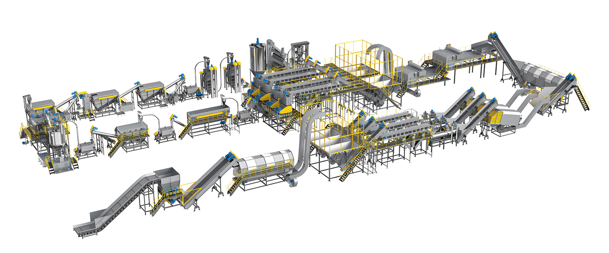
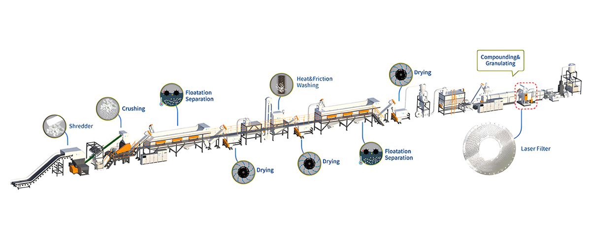
Melt filtration performs best when it is specified together with the washing line that feeds it, which is how Polyretec configures every project. Two product families carry the majority of Polyretec’s melt purification work, and both are supplied with a laser-based continuous screen changer sized to the feedstock rather than to a catalog default.
New Generation Pelletizing Line with laser melt filtration
The New Generation Pelletizing Line is Polyretec’s platform for converting washed flake and regrind into consistent pellets. It is engineered for thin-walled LDPE film as well as thick-walled PE and PP regrind, with a robust construction intended for post-consumer waste rather than clean industrial scrap. The melt filtration stage is the defining element of the line: a laser-based continuous screen changer keeps the pressure differential inside a narrow band so the melt pump, die and pelletizer operate at steady load through long campaigns. Degassing capacity, screw configuration and filtration fineness are matched to the contamination profile of the incoming flake.
| Specification | Compact configuration | Standard configuration | High-output configuration |
|---|---|---|---|
| Throughput | 300 to 600 kg/h | 600 to 1200 kg/h | 1200 to 2500 kg/h |
| Suitable melt temperature range | 180 to 250 °C | 180 to 260 °C | 180 to 260 °C |
| Filtration fineness (disc openings) | 150 to 300 μm | 120 to 250 μm | 100 to 250 μm |
| Pressure differential alarm limit | Configured 100 to 180 bar | Configured 120 to 220 bar | Configured 150 to 250 bar |
| Installed power, filtration stage | Approx. 15 to 30 kW | Approx. 30 to 55 kW | Approx. 55 to 110 kW |
| Typical reject rate | 1 to 4 percent | 0.8 to 3 percent | 0.5 to 2.5 percent |
| Suitable materials | LDPE film, LLDPE, PE regrind | LDPE / HDPE film, PP woven, PP regrind | Mixed PE / PP post-consumer flake |
| Degassing | Single vacuum stage | Single or double vacuum stage | Double vacuum stage |
| Pelletizing method | Strand or water ring | Water ring or die-face hot cut | Die-face hot cut or underwater |
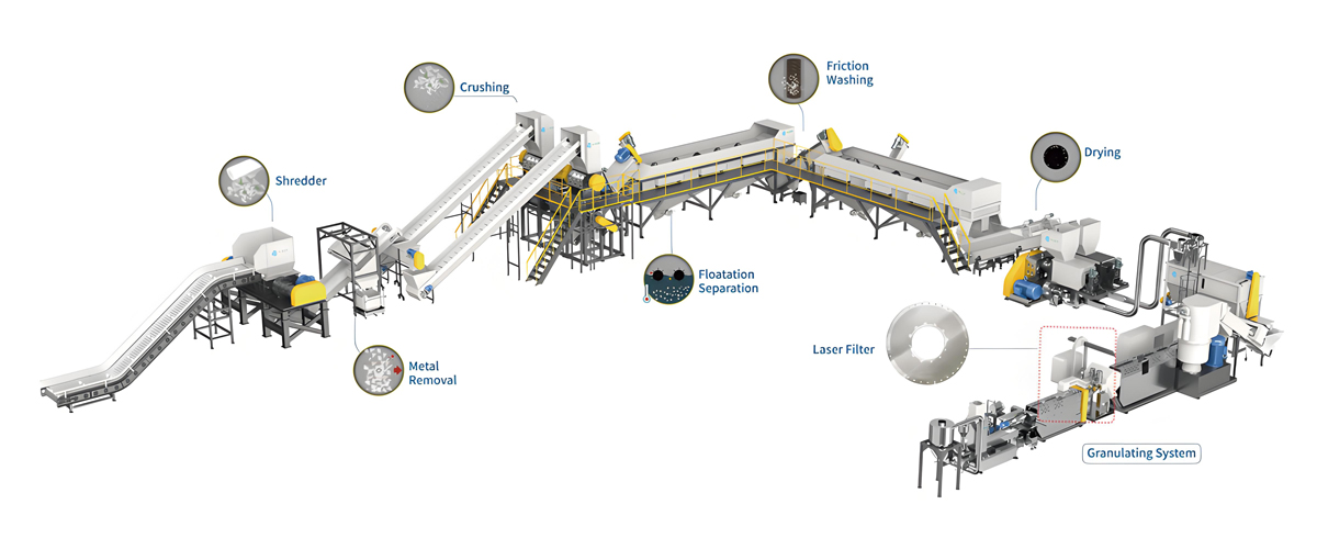
PTW series PP / PE crushing and washing line with one-step pelletizing
The PTW series is Polyretec’s soft plastic crushing and washing platform, engineered for film, woven bags and agricultural film in the 500 to 1500 kg/h class, with a fully automated configuration already proven in export projects. Where the customer wants pellet rather than flake, the line is supplied with one-step pelletizing so that washed, dewatered material moves directly into the extruder and through the laser filtration stage without an intermediate storage step. This is the configuration where melt filtration earns its keep, because agricultural and post-consumer film carries the heaviest load of soil, labels, adhesives and fines.
| Specification | PTW 500 class | PTW 1000 class | PTW 1500 class |
|---|---|---|---|
| Washing line throughput | 500 to 700 kg/h | 800 to 1100 kg/h | 1200 to 1500 kg/h |
| Pelletizing throughput after washing | 350 to 550 kg/h | 600 to 900 kg/h | 900 to 1300 kg/h |
| Suitable melt temperature range | 185 to 245 °C | 185 to 245 °C | 185 to 250 °C |
| Filtration fineness (disc openings) | 200 to 300 μm | 150 to 300 μm | 150 to 250 μm |
| Pressure differential alarm limit | Configured 100 to 160 bar | Configured 110 to 200 bar | Configured 130 to 220 bar |
| Installed power, washing plus filtration | Approx. 110 to 160 kW | Approx. 160 to 260 kW | Approx. 260 to 380 kW |
| Typical reject rate at filter | 2 to 5 percent | 1.5 to 4 percent | 1.5 to 4 percent |
| Suitable materials | LDPE film, shopping bags | Agricultural film, PP woven bags, printed film | Heavily soiled post-consumer film |
| Automation | Semi-automatic | Fully automated | Fully automated with trend logging |
Food grade PET bottle washing line as the feedstock guarantee
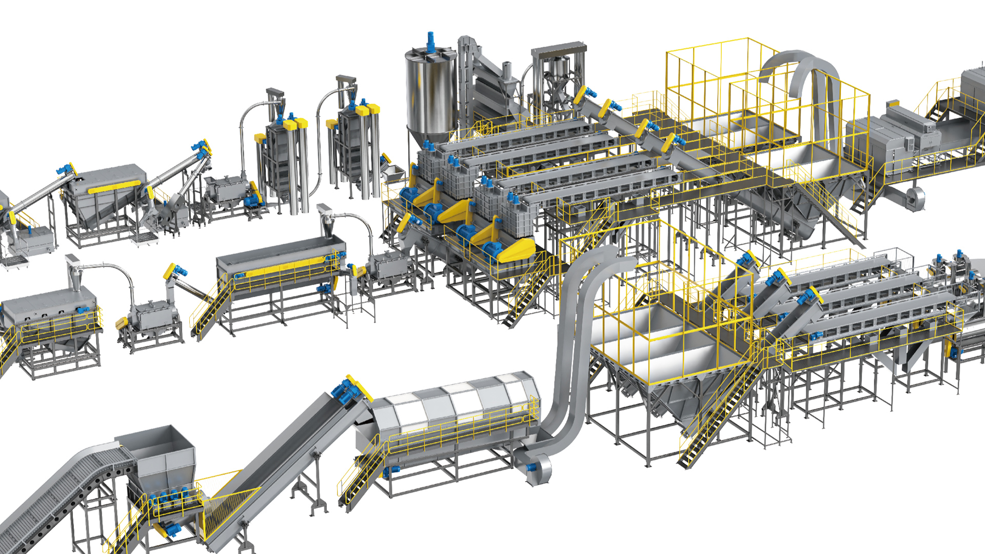
For rPET producers, Polyretec’s Food Grade PET Bottle Washing Line covers 500 kg/h to 6000 kg/h and is designed to deliver different flake grades according to the end application. It is not a filtration machine, but it is the decisive upstream determinant of filtration behavior. PET flake destined for fiber, sheet or bottle-to-bottle applications reaches the melt filtration stage with a residual contamination profile set entirely by how the washing line was configured — label removal efficiency, metal separation, fines extraction and drying performance. Every percentage point of contamination removed there is a percentage point the laser filter never has to handle.
Matching Filtration Fineness to the Downstream Product
Filtration fineness is not a quality contest where finer is always better; it is a balance between the defect tolerance of the end product and the pressure, energy and reject penalty of tighter openings. Selecting an opening size that is two grades finer than the application requires will raise pressure differential, increase shear heating, shorten regeneration intervals and inflate the reject stream without improving the sellable product at all.
| End application | Recommended opening size | Critical contaminant | Consequence of under-filtration | Practical note |
|---|---|---|---|---|
| Heavy-wall PE pipe and profile compound | 250 to 300 μm | Wood, mineral fines | Wall inclusions, weak points | Coarse setting keeps ΔP low and output high |
| Injection molded technical parts from recyclate | 150 to 250 μm | Metal, carbonized specks | Cosmetic specks, crack initiation | Balance against cycle stability |
| Blown film from post-consumer PE | 120 to 200 μm | Gels, crosslinked PE, silicone | Fisheyes, pinholes, bubble instability | Gel content often matters more than fineness |
| rPET flake for fiber and strapping | 150 to 250 μm | Aluminum, PVC fragments, paper | Spinning breaks, yellowing | Pair with strict upstream sorting |
| rPET for sheet and thermoforming | 120 to 200 μm | Black specks, unmelted fractions | Visible defects in clear sheet | Drying quality is equally decisive |
| Recycled PP for woven fabric and tape | 150 to 250 μm | Fillers, degraded fines | Tape breaks at high draw ratio | Consistent melt flow rate is essential |
| Filler-loaded or masterbatch-bound recyclate | 200 to 300 μm | Agglomerates | Dispersion defects | Avoid over-filtering intentional fillers |
One nuance is frequently missed: a laser filter cannot remove dissolved or molecularly dispersed contamination, nor can it remove soft deformable particles smaller than its openings. Odor compounds, migrated additives and low-molecular degradation products pass through untouched. Silicone and rubber can extrude through an opening under pressure and reform downstream. These limitations belong to the process design conversation, not the maintenance conversation, but confusing them causes plants to over-tighten filtration in pursuit of a defect that filtration was never going to solve.
The Laser Filter Maintenance Schedule: Shift to Annual
A laser filter maintained to a written schedule delivers stable purification for years, while one maintained reactively will produce a sequence of unplanned stops that each cost more than the entire annual maintenance program. The schedule below is organized by interval, from every shift to every year, and each task is defined by what to observe, not merely what to do.
Every shift: the four-signal check
Shift-level maintenance takes an operator less than ten minutes and prevents the majority of unplanned stops. Record the pressure differential at a fixed point in the shift under comparable throughput, so the numbers are actually comparable across days. Review the alarm history since the previous shift, including alarms that self-cleared, because a transient high-ΔP alarm that resolved itself is the earliest visible sign of a contamination spike. Collect and weigh the reject discharge and note its appearance: a dry, crumbly reject suggests the discharge zone is running cold, while an excessively wet reject with high polymer content suggests the discharge is over-purging. Finally, confirm melt temperature at the filter inlet and outlet, and note any inlet-to-outlet difference that has grown compared with the baseline, since a widening difference points to increasing shear across a partially blocked disc.
Every week: mechanical confirmation
Weekly tasks verify that the self-cleaning mechanism is genuinely working rather than merely energized. Confirm scraper motion visually where a viewing provision exists, or by drive current signature where it does not — an intact scraping cycle produces a characteristic periodic current pattern, while a slipping or stalled scraper produces a flat or erratic one. Inspect the external condition of all heating zones, including band contact tightness and cable integrity, because a loose band produces a correct control reading with an incorrect actual temperature. Check every static and dynamic seal for weeping polymer; a small bead of polymer at a shaft seal is a warning, and a continuous extrusion of polymer is an immediate stop condition. Verify that the reject discharge path is free and that the collection container has not backed up against the outlet.
Every month: measurement and calibration
Monthly work moves from observation to measurement. Assess pore blockage by comparing the current throughput-to-ΔP ratio with the commissioning baseline; a reduction in effective open area of more than roughly 15 percent should trigger planning for deep cleaning. Lubricate the drive train according to the machine manual, using only the specified high-temperature grease, and record the quantity applied so that over-greasing of sealed bearings is avoided. Verify melt pressure transducers against a reference or, at minimum, confirm the zero reading at ambient with the cavity vented and depressurized. Check thermocouple response by comparing indicated temperature with a calibrated surface probe. Inspect the scraper clearance if the design permits measurement without full disassembly, and log it.
Every quarter: deep cleaning and seal renewal
Quarterly maintenance is a planned stop, and it is where disc life is actually preserved. Deep cleaning of the filter disc must use a process that dissolves or pyrolyzes polymer without attacking the sintered structure: controlled thermal cleaning in a vacuum or fluidized bath at a temperature that decomposes polymer while remaining well below any temperature that would affect the steel, followed by ultrasonic cleaning in an appropriate medium and a verification flow test. Renew the primary shaft seal package and the cavity gaskets as a set rather than individually, because a mixed-age seal set fails unpredictably. Clean and pressure-test the cooling circuit that protects the drive-side bearing and seal, since scale accumulation there is a common root cause of premature seal failure. Inspect the scraper for edge wear and replace it if the wear pattern is uneven across the radius.
Every year: overhaul and life assessment
The annual service is a condition assessment of the whole assembly. Evaluate the filter disc for cumulative degradation: measure open area by flow test, inspect for localized perforation or erosion, and decide between refurbishment and replacement based on measured data rather than appearance. Overhaul the drive gearbox, replacing bearings and gear oil and checking backlash. Recalibrate the entire control system, including pressure transducer spans, temperature loops and the regeneration control logic, and re-record a fresh performance baseline so the next twelve months of trend data have a valid reference. Review the maintenance log as a whole and adjust intervals: a plant running clean washed flake may safely extend quarterly tasks, while a plant running heavily soiled agricultural film may need to compress them.
| Interval | Task | Target / acceptance criterion | Typical duration | Skill level |
|---|---|---|---|---|
| Every shift | Log ΔP at reference throughput | Within baseline band, rise below 2 bar/h | 2 minutes | Operator |
| Every shift | Review alarm history including self-cleared | No repeated transient high-ΔP events | 2 minutes | Operator |
| Every shift | Weigh and inspect reject discharge | Within contracted percentage of throughput | 3 minutes | Operator |
| Every shift | Record inlet and outlet melt temperature | Difference stable versus baseline | 2 minutes | Operator |
| Weekly | Confirm scraper cycle by sight or current signature | Regular periodic pattern present | 15 minutes | Operator / technician |
| Weekly | Inspect heater bands, cables, thermocouple mounting | All zones within ±5 °C, bands tight | 20 minutes | Technician |
| Weekly | Seal and leakage walk-around | No visible polymer weeping | 10 minutes | Technician |
| Monthly | Throughput-to-ΔP ratio versus baseline | Open area loss below 15 percent | 30 minutes | Process engineer |
| Monthly | Drive train lubrication per manual | Specified grease type and quantity only | 30 minutes | Technician |
| Monthly | Verify pressure transducers and thermocouples | Zero and span within tolerance | 45 minutes | Instrument technician |
| Quarterly | Filter disc deep cleaning | Flow test restored to above 90 percent of new | 4 to 8 hours | Specialist |
| Quarterly | Replace shaft seal package and cavity gaskets | Complete set replaced together | 3 to 6 hours | Specialist |
| Quarterly | Clean and pressure-test cooling circuit | No scale, no pressure decay | 2 hours | Technician |
| Annual | Disc life assessment, refurbish or replace | Measured open area and no perforation | 1 to 2 days | Specialist |
| Annual | Drive gearbox overhaul | Bearings, oil, backlash within spec | 1 day | Specialist |
| Annual | Control system recalibration and new baseline | Fresh reference data recorded | 4 to 8 hours | Engineer |
Two rules make this schedule work in practice. First, every measurement must be recorded in a format that permits comparison over months, because the value of a maintenance program lies in the trend and not in the individual reading. Second, intervals must be adjusted from evidence. A schedule copied from a manual and never revised will be either wasteful or insufficient, and usually both at different times of the year as feedstock quality shifts with season and supply.
Filter Disc Life and Failure Modes
A laser sintered disc rarely fails suddenly; it degrades through recognizable modes, each with a characteristic signature that an attentive team can catch months before the disc becomes unusable. Life is measured in operating hours, and with clean washed feedstock and correct regeneration practice a disc commonly delivers several thousand operating hours between refurbishments and can be regenerated repeatedly before final replacement. Heavily contaminated post-consumer material can compress that interval substantially.
| Failure mode | Observable symptom | Root cause | Consequence if ignored | Response |
|---|---|---|---|---|
| Progressive pore blockage | Baseline ΔP climbs steadily over weeks | Carbonized polymer and fines bridging openings | Output loss, shear heating, degradation | Bring quarterly deep clean forward |
| Localized blinding | Reject discharge concentrates on one sector | Uneven melt distribution or scraper clearance drift | Accelerated wear on active sector | Correct clearance, verify inlet flow distribution |
| Local perforation | Contamination appears in pellet at normal ΔP | Erosion by mineral fines or metal impact | Complete loss of filtration integrity | Immediate disc replacement, no repair |
| Uneven scraper wear | Periodic ΔP oscillation synchronized with rotation | Shaft misalignment, worn scraper edge | Disc surface scoring, opening deformation | Replace scraper, check alignment |
| Surface polishing / cold flow closure | Fineness effectively increases, ΔP high, reject low | Scraper set too tight, contact with disc | Permanent reduction of open area | Reset clearance, assess disc by flow test |
| Seal leakage at shaft | Polymer weeping, drive current rising | Seal aging, cooling circuit scaling | Safety hazard, forced stop | Stop, depressurize, replace seal set |
| Thermal stress cracking | Hairline crack visible during service | Rapid heat-up or quench, large radial gradient | Structural failure under pressure | Replace disc, revise heat-up ramp |
| Corrosion pitting | Roughened surface, uneven cleaning result | Halogen-containing contamination such as PVC fragments | Accelerated erosion and blockage | Improve upstream sorting, review disc material |
| Discharge port fouling | Reject flow drops, ΔP rises sharply | Cold discharge zone, hardened reject | Cake buildup and rapid pressure rise | Restore discharge zone temperature, clear port |
The distinction between recoverable and terminal modes governs the maintenance decision. Blockage, blinding and fouling are recoverable through cleaning and adjustment. Perforation, cracking and advanced cold-flow closure are terminal, and continuing to run a perforated disc is worse than running with no filter at all, because the plant believes the material is filtered when it is not. This is why an annual flow test matters: it converts a subjective judgment into a number.
Disc Regeneration and Replacement Done Correctly
Regeneration restores open area without damaging the sintered structure, and the difference between a disc that survives five regeneration cycles and one that is ruined on the first attempt is entirely procedural. There are two regeneration paths — online and offline — and they serve different purposes.
Online regeneration is the continuous scraping and discharge action that the machine performs during production. It removes the soft contaminant layer from the disc face. It does not remove material that has entered and set inside the openings themselves. Increasing regeneration frequency in response to rising pressure differential is correct as a short-term measure, but if the baseline continues to climb after the regeneration rate has been raised, the problem is inside the openings and only offline work will fix it.
Offline refurbishment follows a defined sequence. Remove the disc only after the cavity is fully depressurized and the assembly has cooled to a safe handling temperature, following lockout procedure — high-temperature polymer under pressure is the primary safety hazard on this machine. Remove bulk polymer mechanically using soft tools only. Then apply a thermal cleaning process, typically a vacuum pyrolysis or fluidized bath cycle at a controlled temperature that decomposes the polymer residue, holding time long enough for complete decomposition inside the openings but no longer than necessary. Follow with an ultrasonic bath to remove decomposition ash from the pore structure, then a reverse flow rinse that pushes residue back out through the conical opening profile in the direction opposite to production flow. Verify the result with a flow test at a defined pressure and compare against the value recorded when the disc was new.
Certain practices must never be used. Do not use steel wire brushes, scrapers, needles or any hard metal tool on the sintered surface; a single pass can burr an opening edge and permanently alter the filtration characteristic. Do not use open-flame burn-off, which creates uncontrolled temperature gradients and risks both warping and localized annealing. Do not sandblast or bead-blast, which embeds media in the pore structure. Do not exceed the disc manufacturer’s stated thermal limit in an attempt to shorten cleaning time, because the sintered structure’s dimensional stability depends on never being taken near its transformation range.
The porosity recovery criterion is straightforward: a refurbished disc should restore flow to at least 90 percent of its as-new value at the same test pressure. Between 80 and 90 percent, the disc remains serviceable but should be scheduled for replacement within the next cycle. Below 80 percent, the disc will spend its remaining life forcing the extruder to work against an artificial restriction, and the energy penalty alone justifies replacement. Recording the flow test result at every refurbishment builds a degradation curve that makes replacement timing a planned event rather than a surprise.
Troubleshooting and Fast Recovery
Most laser filter faults present as one of six symptoms, and a structured response gets the line back to specification within hours rather than shifts. The table below is organized so a shift supervisor can move from symptom to action without diagnosis paralysis.
| Symptom | How to confirm | Most likely cause | Corrective action | Typical recovery time |
|---|---|---|---|---|
| Sudden ΔP spike | Step change within minutes at constant throughput | Contamination slug from feedstock, or blocked discharge port | Reduce throughput, raise regeneration rate, verify discharge zone temperature and clear port | 1 to 3 hours |
| Oscillating ΔP | Periodic swing matching scraper rotation period | Uneven scraper clearance or shaft runout | Stop, reset clearance, check alignment and bearing play | 4 to 8 hours |
| Rising reject rate | Reject mass per hour above contracted band for several shifts | Feedstock contamination increase or worn scraper | Sample and analyze flake, then inspect and replace scraper | 2 to 6 hours |
| Melt leakage | Polymer visible at shaft or split line | Seal aging, over-pressure event, bolt relaxation | Immediate controlled stop, depressurize, replace seal set, re-torque to specification | 6 to 12 hours |
| Temperature control instability | Zone deviation above ±15 °C, cycling output | Failed heater band, loose thermocouple, controller tuning drift | Replace heater, remount sensor, retune loop | 2 to 4 hours |
| Black specks increasing in pellet | Visual defect count rising at stable ΔP | Degraded polymer from a dead zone, or disc perforation | Purge cavity thoroughly; if unresolved, inspect disc for perforation | 3 to 10 hours |
| Drive torque high or trip | Motor current above 130 percent of baseline | Hardened cake, bearing damage, seal binding | Stop before torque limiter damage, inspect cavity and bearings | 6 to 16 hours |
| Output drop at unchanged settings | Throughput falls while ΔP rises | Effective open area reduced | Plan deep clean; run at reduced rate in the interim | Interim immediate, full fix at next stop |
One discipline separates strong maintenance teams from weak ones: after every fault, the team records the symptom, the confirmed cause and the corrective action in the same log used for routine measurements. Over a year this becomes a plant-specific reliability database that makes the second occurrence of any fault a thirty-minute event instead of a full-shift investigation.
How Upstream Washing Extends Filter Life
The most effective laser filter maintenance action does not happen at the filter at all — it happens in the washing line, where every percentage point of contamination removed translates into a multiple of additional filter service life. This is the reason Polyretec quotes washing and pelletizing as a matched system rather than as independent machines.
The mechanism is simple arithmetic. A laser filter’s regeneration interval and disc loading are driven by the mass of contaminant arriving per hour. If a line running 1000 kg/h receives flake with 3 percent non-polymer content, the filter must handle 30 kg of contaminant every hour. Reducing residual contamination to 1 percent cuts that to 10 kg per hour. The filter now processes one third of the contaminant mass, so the interval between deep cleans extends correspondingly, the reject stream shrinks, the pressure differential band narrows and the disc spends far less of its life with material set inside its openings.
| Upstream measure | Contaminant targeted | Effect on filter load | Effect on disc service interval | Effect on reject rate |
|---|---|---|---|---|
| Effective pre-sorting and metal separation | Metal, stones, foreign polymer | Removes erosive and perforating particles | Prevents premature terminal failure | Slight reduction |
| Label and adhesive removal | Paper fiber, adhesive residue | Large reduction in carbonizing load | Interval extension of roughly 1.5 to 3 times | Significant reduction |
| Hot friction washing with correct chemistry | Oils, soil, organic residue | Reduces sticky fouling of pore walls | Interval extension of roughly 1.3 to 2 times | Moderate reduction |
| Fines extraction and hydrocyclone separation | Mineral fines, sand | Removes abrasive load | Reduces erosion, extends disc life | Moderate reduction |
| Efficient dewatering and drying | Residual moisture | Prevents hydrolytic degradation and gel formation | Reduces gel-driven blockage | Slight reduction |
| Consistent flake size distribution | Oversize and fines | Stabilizes extruder feeding and melt pressure | Stabilizes ΔP band | Slight reduction |
| Coarse protective screen before fine filtration | Large fragments | Shields the fine disc from shock loads | Meaningful protection against perforation | Neutral |
The practical recommendation follows directly. Before investing in a finer disc or a larger filtration area, audit the washing line. Take a representative sample of washed flake, dry it, and determine non-polymer content by a simple separation and weighing procedure. If that number is above the design assumption used when the filtration stage was sized, the correct fix is upstream. Filtration cannot economically compensate for a washing line running below its capability, and attempting to make it do so is the most common reason plants conclude — wrongly — that their filter is undersized.
Automation, Trend Monitoring and Remote Diagnostics
Modern melt filtration control turns maintenance from a calendar activity into a condition-driven one, because the machine itself generates the data needed to predict its own service needs. The pressure differential signal is the richest source. Logged continuously and normalized against throughput, it produces a degradation curve whose slope forecasts when deep cleaning will be required, typically weeks in advance. A control system that plots ΔP-per-unit-throughput rather than raw ΔP removes the noise created by normal production rate changes and exposes the real trend.
Threshold logic should be layered rather than binary. A single high-ΔP trip that stops the line is a blunt instrument. A better structure uses an advisory level that prompts the operator to raise regeneration frequency, a warning level that schedules an inspection at the next planned stop, and a trip level that protects the equipment. Layering in this way converts most events into planned actions instead of emergency stops.
Consumable forecasting follows the same principle. By logging cumulative operating hours, cumulative throughput and cumulative contaminant mass processed, the control system can estimate remaining life for the disc, scraper and seal set. This transforms the spare parts conversation from guesswork into a schedule, which matters enormously for plants located far from their equipment supplier.
Remote diagnostics closes the loop. Where the plant permits a secure connection, Polyretec engineers can review logged process data, compare it with commissioning baselines and advise on corrective action without waiting for a site visit. In practice most filtration issues are diagnosable from three data streams — pressure differential trend, temperature zone behavior and drive current signature — and a remote review of those streams frequently resolves a problem in hours that would otherwise take days to schedule. Where a site visit is genuinely required, the remote review ensures the engineer arrives with the correct parts already in hand.
Spare Parts Strategy for Uninterrupted Purification
Spare parts planning for a laser filter should be driven by lead time and failure consequence, not by parts count, because the components that stop a line are rarely the ones that fail most often. A seal set costs little and takes minutes to fit, but its absence stops production for as long as it takes to source one. A filter disc is the most significant item in the inventory and the one with the longest replenishment path.
| Component | Failure consequence | Typical replacement driver | Recommended holding level | Notes |
|---|---|---|---|---|
| Laser sintered filter disc | Complete production stop | Annual assessment or perforation | High — one spare on site | Enables refurbishment of the installed disc without downtime |
| Shaft seal package | Forced stop, safety hazard | Quarterly renewal | High — two sets | Always replace as a complete set |
| Cavity gaskets and static seals | Leakage, forced stop | Every cavity opening | High — two sets | Never reuse after disassembly |
| Scraper blade assembly | Rising ΔP, disc damage risk | Wear inspection | Medium — one set | Replace before edge wear scores the disc |
| Melt pressure transducer | Loss of control reference | Drift or diaphragm damage | Medium — one unit | Same range and thread as installed |
| Thermocouples | Temperature control instability | Failure or drift | Medium — full set of one zone type | Inexpensive, high nuisance value |
| Heater bands | Cold zone, discharge blockage | Element burnout | Medium — one per zone size | Discharge zone band is highest priority |
| Drive bearings | Torque rise, seal damage | Annual overhaul | Low to medium — one set | Order with annual service kit |
| Discharge screw or piston | Reject blockage, ΔP spike | Wear over years | Low | Long-lead item, plan ahead |
| Gearbox and drive motor | Complete stop | Rare, long service life | Low | Rely on supplier stock and support |
Polyretec supports this strategy through the Wanplas brand-level spare parts policy of USD 500 free parts/year, plus free replacement of parts damaged within the warranty period. In practical terms this covers the routine consumable items — seals, gaskets, thermocouples and small wear parts — which are precisely the components whose absence causes disproportionate downtime. The recommendation to customers is straightforward: use the annual free parts allocation for the high-frequency, low-value items, and hold the disc and scraper as a planned capital spare.
Energy Use and the Real Maintenance Cost Structure
The energy cost of melt filtration is dominated not by the filter’s own drive motor but by the extruder work required to push polymer through a restricted disc, which means that maintenance quality is directly an energy question. A laser filter drive typically represents a small share of the filtration stage’s installed power, while the pressure the extruder must generate to overcome the disc accounts for the majority of the incremental energy consumption.
| Operating condition | Pressure differential band | Relative specific energy of the filtration stage | Relative maintenance effort | Comment |
|---|---|---|---|---|
| Clean disc, clean flake, correct fineness | 40 to 70 bar | Baseline, roughly 0.02 to 0.05 kWh per kg attributable | Low | Target operating state |
| Moderately loaded disc | 70 to 120 bar | Approx. 1.2 to 1.5 times baseline | Low to medium | Normal working band, monitor trend |
| Heavily loaded disc, deep clean overdue | 120 to 180 bar | Approx. 1.6 to 2.2 times baseline | High | Output loss and shear heating begin |
| Over-fine disc for the application | Elevated at all throughputs | Persistently above baseline | Medium to high | Correct by fineness selection, not maintenance |
| Cold discharge zone | Rapidly rising | Rises sharply with cake buildup | High | Avoidable through weekly heater checks |
| Poorly washed feedstock | Unstable, wide swings | Variable and elevated | Very high | Root cause is upstream, not at the filter |
Maintenance cost itself divides into three categories with very different profiles. Routine consumables — seals, gaskets, sensors and grease — are low in relative cost and highly predictable, and are largely absorbed by the annual free parts policy. Periodic services — quarterly deep cleaning and seal renewal — carry a medium relative cost that is dominated by planned downtime rather than parts. Capital replacements — the disc, gearbox overhaul and drive components — are the high relative-cost category, and their timing is exactly what a good trend record allows a plant to control. The plants with the lowest total maintenance burden are not those that spend the least; they are those whose spending is planned rather than reactive.
Selection Guidance: From Feedstock to Configuration
Configuration should start from the dirtiest material the plant expects to run and the cleanliness the market demands from the finished pellet, since those two endpoints define everything in between. The table below maps common requirement combinations onto Polyretec configurations.
| Feedstock contamination level | Required throughput | Target output cleanliness | Recommended Polyretec configuration | Filtration setup |
|---|---|---|---|---|
| Low — clean in-house film scrap | 300 to 600 kg/h | Standard pellet for non-critical use | New Generation Pelletizing Line, compact configuration | 250 to 300 μm disc, low regeneration frequency |
| Low to medium — sorted industrial regrind | 600 to 1200 kg/h | Consistent pellet for film and injection | New Generation Pelletizing Line, standard configuration | 150 to 250 μm disc, double vacuum degassing |
| Medium — washed post-consumer PE film | 600 to 900 kg/h | Film-grade pellet, low fisheye count | PTW 1000 class washing line with one-step pelletizing | 150 to 200 μm disc, coarse protective screen upstream |
| High — agricultural film with soil and fines | 900 to 1300 kg/h | Pellet for pipe, profile and non-critical molding | PTW 1500 class with heavy-duty pre-washing | 200 to 250 μm disc, elevated regeneration rate |
| High — printed and laminated film | 800 to 1100 kg/h | Consistent color and low speck count | PTW 1000 class with intensified label and ink removal | 150 to 250 μm disc, extended degassing |
| Medium — PET bottle bales, fiber grade output | 1000 to 3000 kg/h | rPET flake for fiber and strapping | Food Grade PET Bottle Washing Line, mid range | 150 to 250 μm at the downstream melt stage |
| Medium to high — PET bales, sheet grade output | 3000 to 6000 kg/h | rPET for sheet and thermoforming | Food Grade PET Bottle Washing Line, high range | 120 to 200 μm, strict drying and sorting upstream |
| Mixed rigid PP / PE regrind | 1200 to 2500 kg/h | Compound-grade pellet | New Generation Pelletizing Line, high-output configuration | 150 to 250 μm disc, die-face or underwater pelletizing |
Two design margins are worth building in from the start. Size the filtration area for the worst feedstock the plant will realistically face, not the average, because a filter sized for average material will spend its bad weeks in the high-pressure regime where wear accelerates. And specify the disc fineness so that at least one coarser and one finer option is interchangeable in the same housing, so the plant can respond to a change in market requirements without changing the machine. Where downstream compounding is part of the plan, Wanplas supplies matched twin-screw pelletizing systems that integrate directly with Polyretec washing lines, keeping the whole chain within one engineering standard.
Applications: Where Purified Recyclate Goes
The purpose of laser filtration is defined by the end market, and Polyretec’s project record spans the main destinations for purified recyclate across renewable resource utilization and plastic product production. Understanding these destinations clarifies why filtration specifications differ so sharply from one plant to the next.
rPET flake and pellet represent the most quality-sensitive destination. Flake produced on a Food Grade PET Bottle Washing Line moves toward fiber spinning, strapping tape, sheet extrusion and thermoforming, and in the most demanding cases toward bottle-to-bottle applications governed by food contact requirements such as FDA and EU 10/2011. Here the limiting contaminants are aluminum flecks from caps and neck rings, PVC fragments that carbonize and yellow the material, and paper fiber from labels. Melt filtration removes what sorting missed, but the tolerance for what passes is measured in parts per million.
Recycled PE and PP film is the highest-volume destination for washed post-consumer film. Purified pellet feeds blown film for refuse sacks, construction sheeting, agricultural film and secondary packaging. The critical filtration issue here is gels and unmelted crosslinked material, because a fisheye in film is immediately visible and immediately rejected. Consistent melt flow rate matters as much as particle removal, since blend variability shows up as bubble instability on the film line.
Recycled engineering material — technical polyolefins, filled compounds and blends destined for injection molded parts — demands the removal of hard inclusions above all, because a metal particle in a structural part is both a cosmetic reject and a mechanical weakness. These streams are usually less voluminous but higher in value, and they justify tighter filtration and a more conservative maintenance interval.
Recycled pellet for pipe, profile and building products tolerates a coarser filtration setting and rewards throughput. Wall inclusions matter structurally, so metal and large wood fragments must be removed, but a 250 to 300 μm setting is usually appropriate and delivers better line economics than an unnecessarily fine disc. Polyretec’s project experience across markets including Turkey, Vietnam, Mexico and Taiwan covers this full spread of destinations, from printed LDPE film recycling systems to PP non-woven and film washing installations.
Service and Support
Equipment reliability is a service outcome as much as an engineering one, and Polyretec structures support around the full life of the line rather than the moment of delivery. Every line is tested before shipment, with the filtration stage run under load so that pressure differential behavior, regeneration cycling, discharge function and control logic are verified in the factory rather than discovered on site. Commissioning data recorded during that test becomes the baseline against which all later trend analysis is measured, which is why customers are advised to keep the factory test report with the machine documentation permanently.
Installation and commissioning are carried out with Polyretec engineers on site. The commissioning scope covers mechanical alignment, heating zone tuning, pressure transducer calibration, establishing the initial ΔP band for the customer’s actual feedstock and setting the layered alarm thresholds described earlier. Operator and maintenance training runs in parallel, covering the shift check routine, safe depressurization and lockout before any cavity is opened, correct seal replacement practice and the flow test procedure used to judge disc condition. Training the maintenance team on the flow test in particular pays for itself, because it removes guesswork from every later refurbishment decision.
Ongoing support draws on the Wanplas brand-level commitments shared across the group: USD 500 free parts/year, free replacement of parts damaged within the warranty period, a transportation guarantee, a production capacity guarantee and quality standards backed by refund with additional compensation if agreed quality is not met. Polyretec’s support team of 24 or more engineers serves customers across more than 50 countries, and remote diagnostic review of logged process data is available for connected installations. The open factory policy stands as well — customers and prospective customers are welcome to visit, watch a line under test and inspect the filtration stage in operation before committing to a configuration.
Frequently Asked Questions
How often should a laser filter be inspected?
Pressure differential, alarm history, reject discharge and melt temperature are checked every shift, which takes under ten minutes. Scraper action, heating zones and seals are inspected weekly. Pore blockage assessment, lubrication and sensor verification are monthly. Deep cleaning and seal renewal are quarterly, and disc life assessment with gearbox overhaul and control recalibration is annual. Intervals should then be adjusted based on your own logged evidence and feedstock quality.
What pressure differential is normal for a laser filter?
A stable working band of roughly 40 to 120 bar across the disc is typical for washed polyolefin flake, with the high alarm configured somewhere between 100 and 250 bar depending on machine design, melt viscosity and disc fineness. The absolute value matters far less than the trend. A baseline that climbs by more than about 2 bar per operating hour at constant throughput indicates progressive pore blockage, and a sudden step change indicates a contamination slug or a blocked discharge path.
How long does a laser sintered filter disc last?
With well-washed feedstock and correct regeneration practice, a disc commonly delivers several thousand operating hours between refurbishments and can be regenerated repeatedly before final replacement. Heavily soiled post-consumer material shortens this substantially. Rather than relying on hours alone, judge the disc by flow test: above 90 percent of as-new flow after refurbishment it is fully serviceable, between 80 and 90 percent schedule replacement, and below 80 percent replace it.
Can a laser filter replace upstream sorting and pre-filtration?
No, and treating it that way is the fastest route to a perforated disc. Metal, stones and large wood fragments must be removed mechanically in the washing line, and a coarse protective screen ahead of the fine filtration stage shields the disc from shock loads. A laser filter is a fine purification stage that handles residual contamination measured in single-digit percentages, not a substitute for mechanical separation.
Why is my reject rate increasing?
Three causes account for most cases. The feedstock contamination load has risen, which a flake sample will confirm within an hour. The scraper edge has worn or its clearance has drifted, so the regeneration cycle discharges more carrier polymer than necessary. Or the control logic has raised regeneration frequency automatically in response to a climbing pressure differential, in which case the reject rate is a symptom and the disc condition is the real issue.
Does upstream washing quality really affect filter life that much?
Yes, and the arithmetic is direct. Filter loading is proportional to contaminant mass per hour, so cutting residual non-polymer content from 3 percent to 1 percent reduces the contaminant the filter must handle to one third. In practice, effective label and adhesive removal alone typically extends disc service intervals by roughly 1.5 to 3 times, which is why Polyretec sizes washing and melt filtration as one matched system.
What should never be done when cleaning a filter disc?
Never use wire brushes, needles, scrapers or any hard metal tool on the sintered surface, because a single pass can burr an opening edge and permanently change the filtration characteristic. Never use open-flame burn-off, which creates uncontrolled thermal gradients. Never sandblast, which embeds media in the pore structure. And never exceed the stated thermal limit of the disc to shorten the cleaning cycle.
Can filtration fineness be changed after the line is installed?
In most configurations yes, provided the alternative disc fits the same housing and the extruder has pressure capability in reserve. This is why Polyretec recommends specifying at least one coarser and one finer disc option as interchangeable at the design stage. Moving to a finer setting raises pressure differential, energy consumption and reject rate, so the change should be justified by a real end-product requirement rather than adopted as a general precaution.
How do I know whether a problem is the filter or the extruder?
Compare the pressure readings on both sides of the disc. If the upstream pressure rises while the differential across the disc stays constant, the restriction is downstream at the die, melt pump or pelletizer. If the differential itself rises, the disc is the restriction. If both the differential and the melt temperature difference across the filter grow together, the disc is blocked enough to be generating significant shear heating and deep cleaning should be brought forward.
Conclusion
Long-term plastic flake purification is a maintenance outcome, not a purchasing decision. A laser filter buys a recycler continuous operation, a narrow and predictable pressure band, low consumable dependency and the ability to process feedstock that would defeat a conventional screen changer — but it delivers those advantages only where the pressure differential is trended rather than merely watched, where the scraper clearance is measured rather than assumed, where deep cleaning follows a procedure that respects the sintered structure, and where the disc is judged by flow test rather than by appearance.
The maintenance program described here is deliberately layered: four signals every shift, mechanical confirmation every week, measurement and calibration every month, deep cleaning and seal renewal every quarter, and overhaul with life assessment every year. Around that core, the two highest-leverage actions sit outside the filter itself — keeping the washing line performing to its design specification so the filter receives the contaminant load it was sized for, and holding the right spare parts so that a small failure never becomes a long stop.
Polyretec, a Wanplas factory, has built plastic recycling equipment since 2010 and delivered more than 100 projects across over 50 countries, engineering washing lines and pelletizing lines with integrated melt filtration as one system. From the New Generation Pelletizing Line for post-consumer PE and PP through the PTW series washing lines with one-step pelletizing to Food Grade PET Bottle Washing Lines running from 500 kg/h to 6000 kg/h, every configuration is matched to a specific feedstock and a specific output quality rather than assembled from a catalog.
If you are specifying a new recycling line, upgrading an existing melt filtration stage or trying to understand why your pressure differential has stopped behaving, send your feedstock description, target throughput and required output cleanliness to the Polyretec engineering team. You will receive a configuration proposal with filtration fineness, operating windows and a maintenance program written for your material — and you are welcome to visit the factory, watch a comparable line under test and see the filtration stage running before you decide.