
Laser filter speed is the single most consequential adjustment an operator makes on a plastic flake purification line, and it is also the one most often left at whatever value the commissioning engineer set on the first day. The scraper rotation speed of a laser filter determines simultaneously how clean the melt is, how much good polymer is thrown away with the contamination, how long the screen disc lasts, and whether the extruder downstream sees a stable or a fluctuating pressure. Set it well and a heavily contaminated post-consumer stream produces pellet with melt loss below 2 percent. Set it badly and the same line either blocks within an hour or discharges a tenth of its throughput into the waste bin.
This guide explains what happens inside a laser filter mechanically, how the four controllable variables — screen disc aperture, scraper speed, discharge valve setting and inlet pressure — interact, and how to calibrate scraper speed systematically against measured contamination load rather than by feel. It is written for production engineers and line operators working with recycled polyolefin and polyester flake, and the parameter ranges given are the practical windows used in commissioning rather than theoretical values. Polyretec, a Wanplas factory specialising in plastic recycling equipment, supplies laser filters as part of integrated washing and pelletizing lines, and the calibration methodology described here reflects that commissioning experience.
The central principle to hold onto throughout is this: scraper speed is not a quality setting, it is a mass balance setting. The scraper must remove contamination from the screen surface at exactly the rate at which the melt stream delivers it. Faster than that and it removes polymer too. Slower and the screen progressively blinds. Every calibration procedure in this article is a method for finding that balance point and holding it as feedstock changes.
What a Laser Filter Is and Where It Sits in the Line
A laser filter, also called a rotary disc filter or continuous melt filter, is a self-cleaning melt filtration device in which contaminated polymer melt is forced through a stationary perforated disc while a rotating scraper continuously removes the retained solids from the upstream face and conveys them to a discharge port. Unlike a screen changer, it never interrupts flow, never requires a screen change during a production run, and can handle contamination levels that would blind a conventional screen pack in minutes.
Position in the Recycling Line
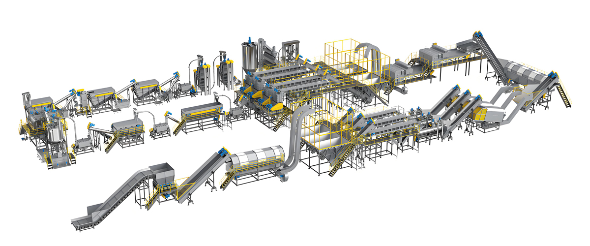
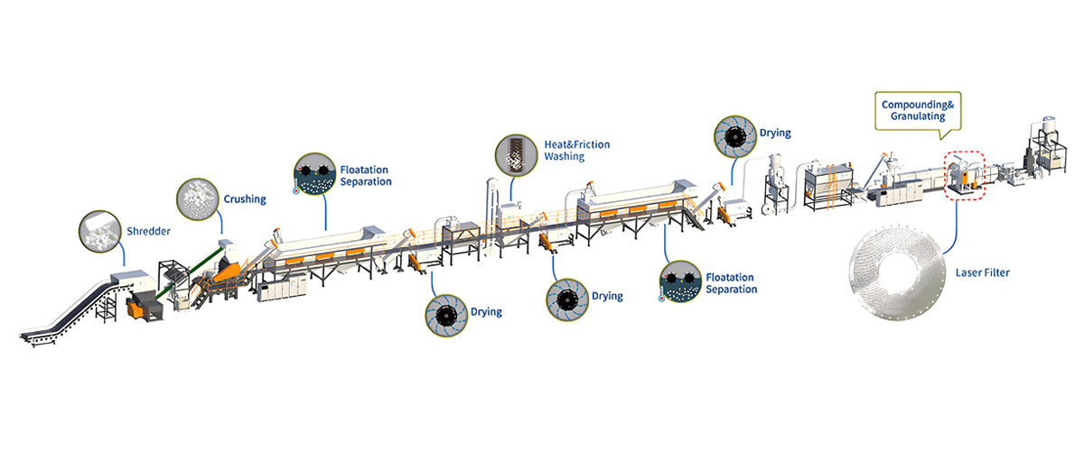
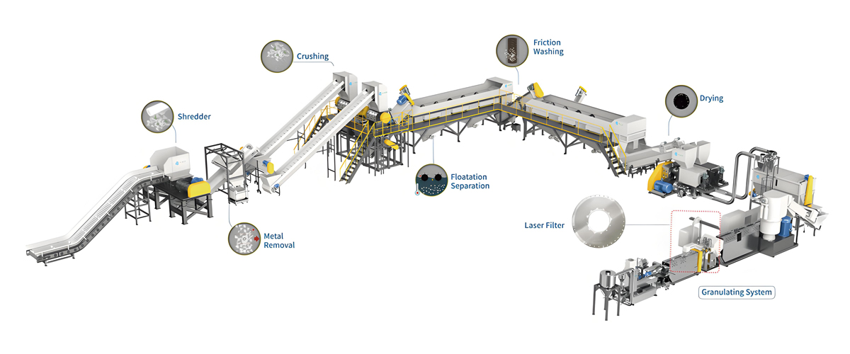
The laser filter is installed between the extruder discharge and the pelletizing die, usually after a melt pump where one is fitted. The typical arrangement in a Polyretec recycling line is:
- Washed and dried flake enters a cutter-compactor or preconditioning unit.
- A single-screw extruder plasticises the material and generates pressure.
- A vacuum degassing zone strips moisture and volatiles.
- The melt passes through the laser filter, where solid contamination is separated.
- A melt pump stabilises pressure to the die, where fitted.
- A water-ring or underwater pelletizer forms the finished pellet.
In some configurations a second, finer polishing filter — a screen changer or candle filter at 40 to 60 micrometres — is installed after the laser filter for applications such as blown film or fibre, where the laser filter does the bulk removal and the polishing stage catches the remainder. This two-stage arrangement is far more economical than trying to achieve fine filtration in a single stage against high contamination.
Why the Rotary Principle Wins Against High Contamination
A conventional screen pack accumulates contamination as a filter cake. Initially the cake improves filtration efficiency, then it raises pressure differential, then it blinds the screen and the run stops. With 2 percent contamination and a 2,000 kilogram per hour throughput, 40 kilograms of solid material arrives at the screen every hour — no static screen area can absorb that. The rotary scraper solves the problem by making the filter cake a transient rather than an accumulating quantity: contamination is removed as fast as it arrives, and the screen surface is continuously renewed.
Competing continuous filtration technologies each solve the same problem differently. Backflush piston screen changers, as built by Nordson, Britas and others, periodically reverse melt flow through a segment of screen to clear it, which consumes a portion of clean product as backflush melt. Gneuss rotary filtration systems index a rotating disc carrying multiple screen cavities through the melt path with integrated backflush. The laser filter is distinguished by its mechanical scraping action, which handles fibrous and ductile contamination such as paper and aluminium foil that resists hydraulic backflushing.
Inside the Screen Disc: Laser-Drilled Hole Geometry
The screen disc is the heart of the filter and its geometry sets the ceiling on what the machine can achieve. Understanding how the holes are made explains several behaviours that otherwise look counter-intuitive.
Why Laser Drilling Rather Than Etching or Weaving
Holes are produced by pulsed laser drilling through a hardened steel disc typically 6 to 12 millimetres thick. Laser drilling produces a conical hole with the narrow opening on the upstream face and a wider bore on the downstream side. This conical geometry is functionally critical for three reasons. First, filtration is determined entirely by the narrow upstream aperture, so the retention rating is precise and repeatable. Second, the widening bore means that once a particle passes the aperture it cannot lodge in the hole — the hole is inherently self-clearing. Third, the pressure drop through the disc is far lower than a straight cylindrical bore of the same length and inlet diameter, because most of the hole length has a larger cross-section.
Woven mesh, by contrast, has a tortuous flow path and traps particles within its depth, which is precisely the behaviour a continuously scraped filter must avoid. Chemically etched plates achieve fine apertures but lack the wall thickness needed to survive 60 bar differential across a large open area.
Aperture Selection by Application
| Hole Diameter | Typical Feedstock | End Application | Typical Differential | Relative Throughput |
|---|---|---|---|---|
| 200 to 250 micrometres | Heavily soiled agricultural film, mixed rigids | Refuse sacks, drainage pipe, pallets | 20 to 40 bar | 100 percent reference |
| 150 to 200 micrometres | Post-consumer PE film, PP woven | Heavy-duty sacks, crates, profiles | 25 to 45 bar | 85 to 95 percent |
| 120 to 150 micrometres | Washed post-consumer HDPE, PP rigids | Bottles, containers, injection parts | 30 to 55 bar | 70 to 85 percent |
| 100 to 120 micrometres | Clean washed flake, post-industrial | Blown film, thin-wall packaging | 35 to 60 bar | 55 to 70 percent |
| 80 to 100 micrometres | Pre-sorted clean flake, rPET | Premium film, sheet, strapping | 40 to 70 bar | 40 to 60 percent |
The relative throughput column is the figure that surprises people. Halving the hole diameter does not halve throughput — it reduces it by considerably more than half at constant differential, because flow through a small orifice scales roughly with the fourth power of diameter under viscous conditions while the number of holes per unit area cannot increase proportionally without compromising disc strength. Specifying a finer disc than the application needs is therefore an expensive decision paid for in permanently reduced line capacity.
Open Area and Disc Strength
Total open area is typically 6 to 14 percent of the disc face. Pushing open area higher weakens the ligaments between holes, and since the disc must withstand the full melt pressure differential across an unsupported span, disc deflection and eventually cracking become the limit. Manufacturers balance this by using thicker discs and higher grade steels for fine apertures. The practical consequence for an operator is that a fine disc has both lower throughput and lower maximum permissible differential, which narrows the operating window from both directions.
Filtration Area Sizing
Effective filtration area is usually quoted in square centimetres. A useful sizing heuristic for polyolefin recycling is 1.5 to 3.0 square centimetres of active screen area per kilogram per hour of throughput for medium contamination, rising to 3.5 to 6.0 square centimetres per kilogram per hour for heavily contaminated material or fine apertures. Undersized filtration area is a design fault that scraper speed cannot compensate for: the operator will find that no speed setting holds the differential in band, because the required flux per unit area is simply too high.
What Scraper Rotation Speed Actually Controls
Scraper rotation speed is often described loosely as controlling cleanliness. It does not. Cleanliness is set by hole diameter. What scraper speed controls is the residence time of the filter cake on the screen surface, and through that, four dependent outcomes.
The Four Dependent Variables
1. Filter cake thickness and pressure differential. Between two passes of the scraper, contamination accumulates on the screen face. At low speed, the cake grows thick and the differential rises. At high speed, the cake is removed almost as soon as it forms and the differential stays close to the clean-screen value. This is the primary control relationship and the one used for calibration.
2. Melt loss to discharge. The scraper cannot remove contamination without also carrying some polymer melt with it. That entrained melt is the discharge loss. The proportion of polymer to contamination in the discharge stream depends on how much contamination has accumulated when the scraper arrives. A thick cake is mostly contamination; a thin cake is mostly melt. Counter-intuitively, running slower can therefore give lower melt loss, provided the differential stays acceptable.
3. Screen disc and scraper wear. Wear is roughly proportional to sliding distance multiplied by contact pressure multiplied by the abrasiveness of the material trapped in the interface. Doubling scraper speed doubles the sliding distance per hour, so it roughly doubles the wear rate, more if the trapped material contains sand or glass. This is why a filter that has been run permanently at maximum speed as a precaution shows disc wear at a third of the expected life.
4. Pressure stability at the die. Each scraper pass momentarily changes the effective open area of the screen, producing a small pressure ripple. At very low speeds this ripple has a long period and can be visible as periodic pellet size variation. At normal speeds the ripple frequency is high enough that the melt pump and die volume damp it out.
Scraper Geometry and Contact Pressure
Most laser filters use one, two or three scraper arms carrying replaceable hardened blades held against the screen face by spring or hydraulic preload. The number of arms matters as much as the rotation speed: a two-arm scraper at 2 revolutions per minute passes any point on the screen four times per minute, exactly as a one-arm scraper at 4 revolutions per minute would, but with half the sliding velocity and therefore lower frictional heating in the interface. When comparing machines from different suppliers, always convert to scraper passes per minute rather than comparing revolutions per minute directly.
Contact pressure is set at assembly and drifts as the blade wears. A blade running with insufficient preload allows a melt film to develop between blade and screen, which prevents effective cake removal — the symptom is a differential that will not come down no matter how much the speed is increased. Blade preload should be checked whenever the differential response to speed becomes sluggish.
Starting Speed by Contamination Class
| Feedstock Class | Contamination (mass percent) | Starting Scraper Speed | Expected Differential | Expected Melt Loss |
|---|---|---|---|---|
| Post-industrial clean regrind | Below 0.1 | 0.3 to 0.6 rpm | 20 to 35 bar | 0.2 to 0.6 percent |
| Washed post-consumer rigids | 0.1 to 0.5 | 0.8 to 1.6 rpm | 25 to 45 bar | 0.8 to 1.8 percent |
| Washed post-consumer film | 0.5 to 1.5 | 1.5 to 3.0 rpm | 30 to 50 bar | 1.5 to 3.0 percent |
| Lightly washed agricultural film | 1.5 to 3.0 | 2.5 to 5.0 rpm | 35 to 55 bar | 3.0 to 5.5 percent |
| Unwashed or heavily loaded stream | 3.0 to 5.0 | 4.0 to 8.0 rpm | 40 to 60 bar | 5.0 to 9.0 percent |
These are starting points for the calibration procedure described later, not final settings. The correct final value always comes from observing the differential response on the actual material.
Melt Pressure Differential as the Master Signal
Melt pressure differential, conventionally written as delta p, is the pressure drop measured between the filter inlet and the filter outlet. It is the only real-time signal that reports the condition of the screen surface, and every automatic control scheme for scraper speed uses it as the feedback variable.
What the Differential Reading Contains
The measured differential is the sum of three components. The clean-screen resistance is a fixed function of hole diameter, open area, melt viscosity and throughput — this is the floor value below which the differential cannot go. The cake resistance is the variable component that scraper speed controls. Transient effects such as a slug of contamination or a viscosity change produce short-term excursions. Distinguishing between these is essential: an operator who responds to a transient spike by permanently increasing scraper speed has traded melt loss for nothing.
| Differential Behaviour | Most Likely Cause | Correct Response |
|---|---|---|
| Stable inside target band | Scraper speed matched to contamination load | No action, log the setting against the feedstock |
| Slow steady rise over hours | Scraper marginally too slow, or gradual disc blinding | Increase speed in 0.2 rpm steps, observe for 20 min each |
| Rapid rise over minutes | Contamination surge, or scraper drive fault | Verify scraper is turning, check feedstock batch change |
| Falls below normal floor | Screen disc worn, holes enlarged, or blade gouging | Inspect product for contamination, plan disc replacement |
| Sawtooth oscillation | Speed too low, cake builds and releases cyclically | Increase speed until oscillation amplitude falls below 5 bar |
| Erratic, no clear pattern | Unstable extruder feed or inconsistent melt temperature | Stabilise the extruder first, then re-tune the filter |
| High but perfectly stable | Aperture too fine, or filtration area undersized | Review disc specification, this is a design not a speed issue |
Setting the Target Band
The target band is bounded below by the clean-screen floor and above by whatever the process can tolerate. Setting the lower bound too close to the floor means the control system will chase noise and drive melt loss up; a sensible lower bound is the clean-screen value plus 8 to 12 bar. The upper bound is determined by three constraints: the mechanical limit of the disc, the melt temperature rise caused by pressure drop, and the pressure the extruder can supply while still meeting throughput.
Melt temperature rise across the filter is a frequently neglected constraint. As a rule of thumb for polyolefins, each 10 bar of pressure drop converts to roughly 0.4 to 0.6 degrees Celsius of adiabatic melt temperature rise. A 60 bar differential therefore adds 2.5 to 3.5 degrees Celsius, which is usually acceptable. But if the filter is being run at 120 bar because the disc is nearly blinded, the resulting 5 to 7 degrees on top of an already-high melt temperature can push a heat-sensitive material past its degradation threshold. Temperature rise is one of the strongest arguments for maintaining the differential in band rather than tolerating creep.
Automatic Versus Manual Speed Control
Modern laser filters offer a closed-loop mode in which the drive adjusts scraper speed to hold a differential setpoint. This is generally the correct mode for production, because it responds to feedstock variation automatically. Two configuration details make the difference between a well-behaved loop and a hunting one. The proportional gain should be modest, since the process has a substantial dead time between a speed change and the resulting differential change — typically 30 to 120 seconds. And the loop should have a rate limit on speed increases, so that a transient contamination slug does not cause a sudden speed jump that dumps polymer to discharge. Manual control remains appropriate during commissioning, during deliberate calibration trials, and when running an unfamiliar feedstock for the first time.
Contamination Load: Paper, Aluminium, Wood and Rubber
Not all contamination behaves the same way at the screen face, and the correct scraper speed depends on the character of the contamination as much as its quantity. Four contaminant classes dominate post-consumer streams and each has distinct filtration behaviour.
Paper and Cellulose Fibre
Paper is the most common contaminant in washed post-consumer flake, arriving from labels, cardboard fragments and fibrous debris. At melt temperature it is partially carbonised and forms a compressible, mat-like cake that is highly effective at blinding a screen — a paper cake of a fraction of a millimetre can double the differential. It is however easy for the scraper to remove because it has low adhesion to the steel face. The correct response to a paper-heavy stream is a moderately high scraper speed with a normal discharge setting. Because paper carbonises, it also contributes directly to black speck counts if any fragment passes the aperture, which is one reason paper-heavy streams justify a finer disc than their nominal application would suggest.
Aluminium Foil
Aluminium arrives from laminated packaging, bottle neck rings and closure liners. It is ductile at melt temperature, so foil fragments can deform and extrude partially into the holes rather than sitting cleanly on the surface. Where a fragment lodges in a hole it may not be removed by the scraper and represents a permanent loss of open area. Aluminium is also abrasive against the blade edge. Streams with significant aluminium content need higher scraper contact pressure, more frequent blade inspection, and benefit from an eddy current separator upstream in the wash line — removing aluminium mechanically before it reaches the melt is always cheaper than filtering it out.
Wood and Hard Mineral Particles
Wood, sand, glass and stone are rigid and abrasive. They do not blind the screen efficiently because they do not form a coherent cake, so their effect on differential is modest relative to their damage potential. The damage is done in the blade-to-screen interface, where a hard particle acts as a lapping abrasive and scores both surfaces. This is the wear mechanism that determines screen disc life in agricultural film recycling. There is no scraper speed that avoids it; the answer is upstream removal through effective pre-washing, sink-float and hydrocyclone stages, plus the acceptance of a shorter disc replacement interval.
Rubber, Silicone and Cross-Linked Polymer
Rubber gaskets, silicone sealants and cross-linked polyethylene fragments are the most difficult class because they are soft and deformable at melt temperature. Under sufficient differential pressure, a rubber particle substantially larger than the aperture can extrude through the hole and reappear as a gel or a soft speck in the finished product. This is the primary failure mode that a laser filter cannot fix by running faster — in fact running the differential high makes it worse, because higher pressure drives more extrusion through the holes. The countermeasures are a finer aperture, a lower and tightly controlled differential, and a lower melt temperature that keeps the elastomer stiffer relative to the polymer matrix.
| Contaminant | Blinding Tendency | Abrasive Wear | Pass-Through Risk | Speed Strategy |
|---|---|---|---|---|
| Paper and cellulose | Very high | Low | Low | Raise speed, normal discharge |
| Aluminium foil | Medium | High | Medium, hole lodging | Moderate speed, higher blade preload |
| Wood fragments | Medium | High | Low | Moderate speed, accept shorter disc life |
| Sand, glass, stone | Low | Very high | Low | Lowest workable speed, remove upstream |
| Rubber and silicone | Low | Low | Very high | Keep differential low, use finer aperture |
| Cross-linked polymer gel | Medium | Low | High | Finer aperture, lower melt temperature |
| Foreign polymer (PET in PE) | High | Low | Low | Raise speed, but fix sorting upstream |
Measuring Contamination Load in Practice
Calibration requires knowing the contamination load, and the simplest reliable method is a discharge mass balance. Collect the filter discharge for a measured interval — 15 to 30 minutes gives a representative sample — weigh it, then wash the collected material in hot xylene or another suitable solvent to dissolve the polyolefin, dry the residue and weigh it. The residue mass divided by the total throughput over the interval gives the true contamination fraction reaching the filter, and the polymer fraction of the discharge gives the melt loss. Repeating this test whenever a new feedstock is introduced converts calibration from guesswork into arithmetic.
Consequences of Running Too Fast or Too Slow
Both errors are common and their symptoms are distinct enough to diagnose from the control screen and the product. Understanding both failure directions is what allows an operator to move confidently towards the optimum rather than nudging cautiously in one direction.
Speed Too Low
The immediate effect is a rising differential. As the cake thickens, several secondary consequences follow. Melt temperature rises through the increased pressure drop, adding thermal stress to material that has already been through multiple heat histories. Extruder output falls, because the screw must work against higher head pressure and the pressure-flow characteristic of a single screw is not stiff. Motor load rises, and on lines where the extruder is already near its torque limit, the drive may trip. Filtration efficiency actually improves temporarily as the cake acts as a depth filter, which misleads operators into thinking the situation is benign. Eventually the differential reaches the alarm limit and either the line is stopped or the scraper is driven up sharply, producing a large slug of discharge and a pressure transient at the die that shows as pellet size variation.
A subtler consequence of chronic under-speed operation is permanent hole blinding. Material that sits on the screen for extended periods carbonises and can bond into the hole entry. Once that has happened, the clean-screen floor differential has permanently risen and the disc will never recover to its original performance even after a full clean.
Speed Too High
The immediate effect is elevated melt loss, which is money leaving the building continuously and quietly. On a 1,500 kilogram per hour line, the difference between 2 percent and 6 percent melt loss is 60 kilograms of saleable pellet per hour. Because the discharge is a mixed polymer-contaminant stream, it cannot usually be reprocessed and goes to waste disposal, adding a cost on both sides of the balance.
Wear accelerates in proportion to sliding distance. A screen disc that would give 3,000 hours at 1.5 revolutions per minute may give barely 1,000 hours at 5 revolutions per minute on the same material. Blade replacement intervals shorten similarly. In severe cases the blade begins to gouge the screen face, producing local depressions where melt bypasses the intended aperture and contamination passes into the product — a failure mode that presents as product contamination while the differential reads normal or low, which is one of the most confusing symptoms to diagnose.
There is also a pressure consequence. Excessive discharge reduces the melt flow reaching the die, so at constant extruder output the die pressure falls. On lines without a melt pump this changes throughput and pellet dimensions; on lines with a melt pump the pump inlet pressure may drop below its minimum, causing cavitation and pump wear.
| Symptom | Speed Too Low | Speed Too High |
|---|---|---|
| Melt pressure differential | Rising, often with sawtooth pattern | At or below clean-screen floor |
| Discharge appearance | Dark, dry, mostly contaminant | Light coloured, mostly polymer |
| Melt loss | Below 1 percent | Above 5 percent |
| Melt temperature at die | Rising above setpoint | Normal or slightly low |
| Extruder motor load | Rising | Normal |
| Screen disc life | Reduced by carbonisation and blinding | Reduced by abrasive wear |
| Product defects | Yellowing, black specks from degradation | Contamination pass-through if blade gouges |
| Pellet consistency | Periodic size variation | Throughput drift, low die pressure |
Step-by-Step Speed Calibration Procedure
The following procedure establishes the correct scraper speed for a given feedstock and records it so that the setting can be recalled rather than rediscovered. It takes approximately three hours of stable running and should be repeated whenever a materially different feedstock enters the line.
Prerequisites
- Extruder running at the intended production throughput with stable feed and motor load.
- Melt temperature at setpoint and stable within plus or minus 2 degrees Celsius for at least 30 minutes.
- A freshly cleaned or new screen disc of the correct aperture for the application.
- Inlet and outlet melt pressure transducers calibrated and reading correctly.
- A means of collecting and weighing the discharge stream.
- Feedstock representative of what production will actually run, not a clean sample.
Step 1: Establish the Clean-Screen Floor
With a clean disc at production throughput and scraper running at a deliberately high speed of 4 to 6 revolutions per minute, allow the differential to settle for 15 minutes. The stable value is the clean-screen floor for this combination of material, aperture, temperature and throughput. Record it. Typical floor values are 15 to 25 bar for a 150 micrometre disc on polyolefin at moderate throughput. This number is the reference against which all subsequent readings are interpreted, and it should be re-measured whenever the disc is changed.
Step 2: Define the Target Band
Set the lower bound at the floor plus 10 bar and the upper bound at the floor plus 30 to 35 bar, subject to not exceeding the disc manufacturer’s maximum differential and not exceeding the melt temperature rise the material tolerates. For a floor of 20 bar this gives a target band of 30 to 55 bar.
Step 3: Reduce Speed in Steps
From the high starting speed, reduce the scraper speed in decrements of 0.3 to 0.5 revolutions per minute. After each decrement, wait a full 20 minutes before reading the differential — the system dead time means a reading taken after 5 minutes will understate the eventual steady-state value and will lead to setting the speed too low. Record scraper speed and stabilised differential at each step. Continue until the differential reaches the upper bound of the target band.
Step 4: Identify the Knee
Plot differential against scraper speed. The curve is characteristically flat at high speeds and rises steeply below a certain point — the knee. The optimum operating speed is just above the knee, where the differential sits in the middle of the target band and where a small drop in speed does not cause a large rise in differential. Operating on the flat portion far above the knee wastes polymer; operating below the knee is unstable because small feedstock variations produce large differential swings.
Step 5: Verify Melt Loss
At the chosen speed, run for 30 minutes and collect the entire discharge. Weigh it and express it as a percentage of throughput over the interval. If melt loss exceeds the expected range for the contamination class, the speed is above optimum or the discharge valve is open too wide; return to step 3 and re-examine. If melt loss is well below expectation while the differential is stable, the feedstock is cleaner than assumed and the speed can be reduced further with benefit.
Step 6: Verify Product Quality
Take pellet samples and run the quality checks relevant to the application: visual speck count on a pressed film, melt flow rate, and where applicable a gel count on a cast film sample. Confirm that the reduced speed has not allowed contamination through. If specks appear, the cause is more likely aperture selection or blade condition than speed, so inspect the disc and blade before increasing speed.
Step 7: Record and Transfer to Automatic Control
Log the feedstock description, throughput, melt temperature, aperture, floor differential, chosen speed and measured melt loss in a recipe record. Set the automatic controller’s differential setpoint to the value achieved and enable closed-loop control with the speed limits bracketing the manual value by plus or minus 40 percent. The recipe becomes the starting point for the next run of the same material, reducing calibration to a verification exercise.
Discharge Rate and Melt Loss Optimization
Scraper speed and discharge rate are separate but coupled adjustments, and confusing them is a frequent source of poor filter performance. Scraper speed determines how much material is scraped off the screen face; the discharge arrangement determines how much of that material actually leaves the machine and how much recirculates within the filter housing.
Discharge Mechanisms
Laser filters use one of three discharge arrangements. A discharge screw conveys scraped material out of the housing at a rate set by its own speed, giving independent control of discharge volume. A pressure-regulated discharge valve opens against melt pressure, so discharge rate follows housing pressure. A timed piston discharge ejects a fixed volume at a set interval. Each requires a different tuning approach.
With a discharge screw, the correct setting is one at which the scraped material is removed without accumulating in the collection zone, but no faster. Running the discharge screw too fast draws additional melt from the housing and inflates melt loss independently of scraper speed — the classic symptom is high melt loss with a discharge stream that looks almost clean. Running it too slowly allows scraped material to build up in the housing, where it re-enters the scraper path and is repeatedly worked, generating heat and degrading into black specks that eventually pass into the product.
Coupled Tuning Sequence
Because the two adjustments interact, the correct sequence is to fix one and tune the other, then verify. In practice:
- Set the discharge mechanism to a nominal mid-range value.
- Calibrate scraper speed against differential using the procedure in the previous section.
- With scraper speed fixed, reduce discharge rate in small steps while watching for material accumulation in the housing — visible as a slow rise in housing pressure or, on machines with a sight port, directly.
- Set the discharge just above the point where accumulation begins.
- Re-verify the differential, since a change in discharge rate slightly changes the effective housing conditions.
- Re-measure melt loss and confirm the improvement.
Melt Loss Targets and What Drives Them
| Contamination Load | Achievable Melt Loss | Polymer Fraction of Discharge | Main Lever if Above Target |
|---|---|---|---|
| Below 0.1 percent | 0.2 to 0.6 percent | 70 to 85 percent | Reduce scraper speed towards minimum |
| 0.1 to 0.5 percent | 0.8 to 1.8 percent | 55 to 75 percent | Reduce discharge screw speed |
| 0.5 to 1.5 percent | 1.5 to 3.0 percent | 45 to 65 percent | Verify scraper is above knee, not far above |
| 1.5 to 3.0 percent | 3.0 to 5.5 percent | 35 to 55 percent | Improve upstream washing and sorting |
| 3.0 to 5.0 percent | 5.0 to 9.0 percent | 25 to 45 percent | Upstream removal is the only real fix |
The polymer fraction of the discharge is a more informative diagnostic than melt loss alone. If the discharge is 80 percent polymer on a moderately contaminated stream, the filter is throwing away good material and the settings are wrong. If the discharge is 25 percent polymer on a lightly contaminated stream, either the contamination measurement is wrong or the scraper is barely keeping up and the differential should be checked.
Discharge Handling
Filter discharge leaves the machine at melt temperature as a hot, sticky, contaminated mass. Good practice is to discharge into a water-quenched conveyor or a chilled roll that solidifies it into a manageable ribbon, weigh it continuously with a belt scale, and log the mass flow as a process variable. A continuously logged discharge mass is the fastest way to spot a filter that has drifted off setting, and it converts melt loss from a periodically measured quantity into a live indicator.
Screw Back Pressure, Melt Temperature and Filter Interaction
The laser filter does not operate in isolation. Three extruder-side variables directly determine what the filter sees and how well it can perform, and tuning the filter without controlling them produces settings that will not hold.
Back Pressure and Inlet Pressure Stability
Screw back pressure, generated by the resistance downstream of the metering section, determines the pressure at which melt is delivered to the filter. Adequate back pressure serves three purposes at the filter: it ensures the melt is fully compacted and free of entrained gas that would otherwise cause pressure noise, it provides a stable driving pressure so that differential readings reflect cake condition rather than feed fluctuation, and it improves melt homogeneity so that viscosity — which directly affects differential — stays constant.
For recycling extruders, typical back pressure at the filter inlet is 80 to 180 bar for polyolefins. Below roughly 60 bar the differential signal becomes noisy and closed-loop speed control hunts. Above 200 bar the additional shear heating begins to raise melt temperature unnecessarily and increases the risk of soft contaminants extruding through the apertures.
Melt Temperature Effects
Melt temperature affects filtration through viscosity. A 10 degree Celsius increase reduces polyolefin melt viscosity by roughly 15 to 25 percent depending on the material and shear rate, which reduces the differential at a given throughput and cake condition. This creates a trap: an operator seeing a high differential may raise melt temperature to bring it down, which appears to work but has not removed any contamination — it has merely made the melt thinner. The cake is still there, wear is still occurring, and now the material is being thermally stressed as well. Differential should be corrected by scraper speed, not by temperature.
The reverse trap also exists. Reducing melt temperature to protect a heat-sensitive material raises viscosity and therefore differential, and the operator may respond by increasing scraper speed and accepting the extra melt loss when the real answer is to verify the filtration area is adequate for the intended operating temperature.
| Material | Melt Temperature Window | Filter Inlet Pressure | Target Differential | Special Note |
|---|---|---|---|---|
| Recycled LDPE / LLDPE | 180 to 210 degrees C | 90 to 160 bar | 30 to 55 bar | High viscosity, generous filter area needed |
| Recycled HDPE | 190 to 225 degrees C | 100 to 180 bar | 30 to 60 bar | Watch for gels from cross-linked fraction |
| Recycled PP | 200 to 235 degrees C | 80 to 150 bar | 25 to 50 bar | Lower viscosity, easier filtration |
| Recycled PS | 190 to 220 degrees C | 70 to 130 bar | 20 to 45 bar | Heat sensitive, avoid high differential |
| Recycled PET | 270 to 285 degrees C | 60 to 120 bar | 25 to 45 bar | Low viscosity, residence time critical for IV |
Residence Time in the Filter Housing
The filter housing adds volume to the melt path and therefore adds residence time. For polyolefins at moderate temperature this is unimportant. For polyester it matters considerably, because every additional second at 280 degrees Celsius contributes to intrinsic viscosity loss through thermal and hydrolytic degradation. Filters for polyester duty are designed with streamlined internal geometry and minimal dead volume for exactly this reason, and a general-purpose polyolefin filter should not be assumed suitable for rPET service without checking the housing volume against the throughput.
Interaction with the Degassing Zone
Because the filter sits downstream of the vacuum degassing zone, any change in filter differential changes the pressure profile back along the screw, including at the vent. A large differential increase can raise the pressure at the vent to the point where melt is pushed into the vacuum port — vent flooding. If a line begins flooding its vacuum vent after weeks of stable operation, a blinding filter disc is a prime suspect and should be checked before the screw geometry is blamed.
Troubleshooting Matrix for Unstable Filtration
Most laser filter problems present as one of eight symptoms. The following matrix maps each to its likely causes in order of probability, with the check that distinguishes between them.
| Symptom | Probable Causes in Order | Distinguishing Check | Action |
|---|---|---|---|
| Differential climbs despite max speed | Disc blinded; blade preload lost; filter area undersized | Compare current floor to commissioning floor | Clean or replace disc, check blade spring |
| Melt loss above 6 percent | Speed above knee; discharge screw too fast; worn blade | Measure polymer fraction of discharge | Re-run calibration steps 3 to 5 |
| Contamination in product, normal differential | Screen gouged; hole enlargement; bypass at seal | Remove and inspect disc face under light | Replace disc, inspect blade and seals |
| Black specks appearing gradually | Material stagnating in housing; discharge too slow | Check discharge mass against expected | Raise discharge rate, plan housing clean-out |
| Soft gels in film product | Rubber extruding through holes; aperture too coarse | Solvent test a gel to identify elastomer | Finer disc, lower differential and temperature |
| Scraper drive overload trip | Hard object jammed; excessive blade preload; cold housing | Check all housing heater zones at setpoint | Heat soak fully before restart, inspect for debris |
| Closed-loop speed hunting | Controller gain too high; unstable extruder feed | Switch to manual, see if differential steadies | Reduce gain, add rate limit, fix feed first |
| Vacuum vent flooding | Filter differential too high, backing pressure up the screw | Correlate flooding events with differential log | Restore differential to band, service disc |
The Diagnostic Value of the Commissioning Record
Almost every entry in that matrix is resolved faster if the commissioning floor differential, scraper speed and melt loss were recorded for each material. Without that baseline, an operator cannot distinguish a filter that is performing normally on difficult material from one that has degraded on easy material. Establishing and preserving the baseline record is the highest-value ten minutes of work in the whole commissioning process.
Maintenance Intervals and Screen Disc Replacement
Laser filter maintenance divides into three cycles: daily observation, periodic component inspection, and screen disc replacement driven by condition rather than calendar.
Recommended Intervals
| Task | Interval | What to Check | Action Trigger |
|---|---|---|---|
| Differential log review | Every shift | Trend against baseline, oscillation amplitude | Floor risen more than 10 bar above baseline |
| Discharge mass check | Every shift | Mass per hour versus recipe value | Deviation beyond 25 percent |
| Housing heater verification | Weekly | All zones reaching setpoint, no failed elements | Any zone more than 8 degrees C off setpoint |
| Scraper blade inspection | 400 to 800 hours | Edge condition, wear step, preload force | Visible edge rounding or preload loss |
| Drive gearbox service | 2,000 to 4,000 hours | Oil condition, backlash, seal integrity | Per gearbox manufacturer schedule |
| Pressure transducer calibration | 6 months | Zero offset, span against reference | Drift beyond 3 percent of span |
| Screen disc replacement | 800 to 4,000 hours | Thickness, hole geometry, surface scoring | Condition-based, see criteria below |
| Full housing clean-out | With each disc change | Dead-zone deposits, seal faces | Always, do not defer |
Disc Replacement Criteria
Replace the screen disc when any one of the following is true. First, the clean-screen floor differential measured after a full clean has risen more than 40 to 50 percent above the original commissioning value, indicating permanent hole blinding or partial closure. Second, disc thickness measured at several radii has fallen below the manufacturer’s minimum, which is typically 15 to 20 percent below new thickness. Third, contamination is passing into the product while the differential reads normal, indicating hole enlargement or surface scoring. Fourth, the surface shows visible circumferential grooving deep enough to be felt with a fingernail, which means the blade is no longer sealing across the full face.
Disc life varies enormously with abrasive load. Clean post-industrial polyolefin can give 3,000 to 4,000 hours. Washed post-consumer rigids typically give 1,800 to 3,000 hours. Agricultural film with residual sand can reduce life to 800 to 1,500 hours. The strongest lever on disc life is not the filter at all — it is the effectiveness of upstream sand and grit removal in the washing line, which is why washing line design and filter economics are directly connected.
Cleaning Rather Than Replacing
Discs that are worn but not damaged can often be regenerated. Established methods are pyrolytic cleaning in a vacuum oven at 400 to 450 degrees Celsius to decompose the polymer, followed by ultrasonic cleaning to remove ash, and in some cases high-pressure water jetting. Regeneration typically restores 85 to 95 percent of original flow capacity and can be repeated two or three times before the disc must be scrapped. It is standard practice to hold at least one spare disc so that a change can be made during a planned stop rather than an unplanned one, with the removed disc sent for regeneration.
Safety During Disc Change
Screen disc replacement involves opening a housing that contains polymer melt above 200 degrees Celsius under residual pressure. The sequence must include stopping the extruder, allowing pressure to decay and verifying it at the transducer, isolating and locking out the scraper drive and all heater circuits according to site procedure, allowing controlled cooling where the housing design requires it, and using appropriate heat-resistant gloves, face protection and long sleeves. Melt under pressure can eject violently from a partially opened flange, and this is the single highest-risk routine task on a recycling line. Never loosen housing fasteners while the pressure transducer reads above zero.
Selecting a Laser Filter with Polyretec
Polyretec, a Wanplas factory, supplies laser filters both as components within complete recycling lines and as standalone units for retrofit onto existing extruders. Correct selection depends on four inputs, and providing them accurately at enquiry stage avoids the most common specification errors.
The Four Selection Inputs
Throughput. State the required throughput in kilograms per hour of melt actually passing the filter, and state whether that is a nominal or a peak figure. Filters sized on nominal throughput and then run at peak will spend their life at the top of the differential band.
Polymer and melt viscosity. Provide the polymer type and, where known, the melt flow rate of the feedstock. A low melt flow rate material — for example an HDPE at 0.3 grams per 10 minutes — requires substantially more filtration area than a 8 grams per 10 minute grade at the same throughput and aperture.
Contamination profile. Provide both the total contamination fraction and its composition. As the earlier section showed, 1 percent sand and 1 percent paper make very different demands on the machine. A physical sample of the flake is more informative than any description.
Product quality requirement. State the end application and, if possible, the acceptance criterion — speck count per unit area, gel count, or a customer specification. This drives aperture selection, and aperture selection drives everything else.
Integration Considerations for Retrofit
Retrofitting a laser filter onto an existing extruder requires checking three things beyond the filter itself. The extruder must be able to generate the required inlet pressure at production throughput, which for a machine previously running with a low-resistance screen changer is not automatic. The melt path geometry between extruder and filter must avoid dead zones, since a poorly designed adapter is a black speck factory that will be blamed on the filter. And the control system must be able to accept the differential signal and, ideally, host the closed-loop speed control, or the filter must be supplied with its own controller.
Where the Filter Sits in the Wanplas Product Range
Polyretec builds washing lines from 300 to 6,000 kilograms per hour and pelletizing lines from 200 to 2,500 kilograms per hour, with laser filtration specified to match the contamination profile of each project. As part of the Wanplas brand, lines are supplied under a documented quality system with CE conformity where the destination market requires it, factory acceptance testing before shipment, installation supervision and operator training that covers the calibration logic described in this article rather than only the button sequence. Where the recycled pellet feeds a compounding step, Wanplas’s Kerke factory supplies twin-screw extruders that integrate downstream of Polyretec systems, and where it feeds container production, the Apollo and YuDa factories supply blow moulding equipment. The Wanplas commitment to warming global customers with China plastic machinery is expressed in long-term spare parts availability, which for a laser filter means screen discs and scraper blades remaining obtainable throughout the machine’s service life.
Frequently Asked Questions
How often should scraper speed be re-optimised?
Re-run the full calibration whenever the feedstock changes materially — a different supplier, a different collection stream, or a visible change in contamination. For a stable feedstock, verify the settings monthly by checking that the differential is still holding in band at the recorded speed and that discharge mass matches the recipe. If closed-loop control is enabled, review the average speed the controller is selecting: a gradual upward drift over weeks indicates the disc is approaching the end of its life.
Can the same laser filter run both polyolefin and polyester?
Mechanically yes, but it requires a full changeover procedure and the housing volume should be checked for polyester suitability. The practical obstacles are the large temperature difference, roughly 200 degrees Celsius for polyolefin against 280 for polyester, and the purging effort needed to prevent cross-contamination, since residual polyolefin in a polyester melt appears as unmelted specks and vice versa. Plants running both polymers regularly are better served by dedicated filters.
Is a melt pump necessary after a laser filter?
Not strictly necessary, but strongly recommended for any application where output consistency matters. Without a melt pump, every variation in filter differential translates directly into a variation in die pressure and therefore in throughput and pellet size. A melt pump decouples the two, holding die pressure constant while the filter differential fluctuates. For food-grade and premium applications a melt pump is effectively standard.
What is the relationship between laser filter aperture and gel count?
The relationship is real but weaker than many assume, because most gels in recycled polyolefin are cross-linked polymer that is soft at melt temperature and can deform through an aperture considerably smaller than the gel’s nominal diameter. Reducing aperture from 150 to 100 micrometres typically reduces gel count by 30 to 50 percent rather than eliminating gels. Meaningful gel reduction usually requires attacking the source: reducing thermal history, improving degassing, and avoiding cross-linked material in the feedstock.
Why does the differential sometimes fall unexpectedly during a run?
Three explanations account for most cases. A viscosity drop from rising melt temperature or a change to a higher melt flow rate feedstock reduces differential without any change in cake condition. A drop in throughput, for instance from feed starvation, reduces flux through the screen. Or the disc has developed a flow path it should not have, through hole enlargement, scoring or a seal bypass. The first two are benign and self-explanatory from the other instruments; the third requires immediate product inspection, because it means unfiltered melt is reaching the pelletizer.
Should scraper speed be increased during start-up?
Yes. During start-up the melt is often colder and more viscous than at steady state, and the first material through the machine frequently carries accumulated debris from the previous shutdown. Running the scraper at 1.5 to 2 times the production setting for the first 20 to 30 minutes clears this and prevents the disc starting the run already partly loaded. Reduce to the calibrated setting once melt temperature and differential have both stabilised.
How does throughput change affect the calibrated speed?
Contamination arrives at the screen in proportion to mass throughput, so a 20 percent throughput increase delivers 20 percent more contamination per unit time and requires roughly 20 percent more scraper speed to maintain the same cake condition. However, the higher throughput also raises the clean-screen floor differential, so the target band shifts upward as well. The practical approach is to record calibrated settings at two or three throughputs and interpolate, rather than assuming a single setting covers the whole operating range.
Can filtration be improved without changing the disc?
Within limits, yes. Stabilising melt temperature reduces viscosity swings and therefore differential noise, letting the filter run closer to its optimum. Improving upstream washing and sorting reduces the load the filter must handle, which is always the highest-leverage intervention. Ensuring adequate and stable back pressure improves melt homogeneity. And correcting blade preload restores scraping effectiveness that may have degraded unnoticed. Only after these are addressed does a finer disc become the right answer.
What data should be logged for process traceability?
At minimum, log filter inlet pressure, outlet pressure, calculated differential, scraper speed, discharge mass flow and housing zone temperatures, all time-stamped and retained. For lines pursuing food-grade authorisation, this data forms part of the evidence that the process ran within its authorised window. Even without a regulatory driver, a differential and speed history is the fastest diagnostic tool available when quality problems surface days after the batch was produced.
Conclusion
Optimising laser filter speed is a mass balance exercise disguised as a machine setting. The scraper must remove contamination at the rate the melt stream delivers it — no faster, no slower — and every symptom of poor filter performance traces back to a departure from that balance in one direction or the other. Too slow and the differential climbs, melt temperature rises, throughput falls and the disc eventually blinds permanently. Too fast and good polymer leaves with the waste, wear accelerates, and the pressure the pelletizer depends on becomes unreliable.
The method for finding the balance is not complicated but it does require discipline: establish the clean-screen floor on a fresh disc, define a target band 10 to 35 bar above it, step the speed down while allowing a full 20 minutes for each reading to settle, find the knee in the differential curve, verify melt loss by weighing the discharge, confirm product quality, and record everything as a recipe so it never has to be rediscovered. Applied consistently, this procedure typically moves melt loss on washed post-consumer material from an uncontrolled 4 to 6 percent down to a controlled 1.5 to 3 percent while extending screen disc life materially.
Equally important is knowing what scraper speed cannot fix. Aperture selection sets the cleanliness ceiling. Filtration area sets the throughput ceiling. Rubber and cross-linked gels pass through under high differential regardless of how fast the scraper turns. Abrasive sand destroys discs whatever the setting. Each of these is an upstream or specification issue, and recognising them quickly prevents an operator from spending weeks adjusting a variable that was never the constraint.
Polyretec, a Wanplas factory, specifies laser filtration against the actual contamination profile of each project rather than a catalogue default, and supports commissioning with the calibration methodology described here. Operators planning a new pelletizing line, or troubleshooting an existing filter that has drifted from its original performance, are encouraged to share their feedstock analysis, throughput target and current differential record so that the specification or the correction can be based on the material as it really is.