
Metal contamination is the single most destructive and most under-engineered risk in a plastic recycling washing line. A single 30 mm bolt hidden inside a baled PET bottle stream can chip four blades in a wet crusher, gouge the auger flight of a friction washer, blind a melt filter screen within minutes, and end up as a hard inclusion in a finished pellet that a food-grade buyer will reject on arrival. Knowing how to integrate metal detector hardware into a plastic recycling washing line is therefore not an accessory decision — it is a core process engineering decision that determines blade life, screen changer duty, energy consumption, and whether recycled resin can be sold into food-contact applications at all. This guide walks through the complete washing process chain stage by stage, identifies exactly where ferrous, non-ferrous and stainless contamination enters, compares six detection and separation technologies with real sensitivity figures, and then sets out a validated five-point installation layout with the interlock logic, reject timing calculations, electromagnetic interference countermeasures and calibration routines required to make it work in a wet, vibrating, inverter-driven industrial environment. The content reflects the design practice used by Polyretec, a Wanplas factory that has been building washing and pelletizing lines since 2010 and has delivered more than 100 recycling projects across over 50 countries.
Why Metal Contamination Decides Washing Line Profitability
Metal is the only contaminant in a post-consumer plastic stream that can destroy capital equipment in a single event rather than degrading it gradually. Everything else — paper labels, sand, oil, food residue, wrong-polymer fragments — is handled statistically by the process. Metal is a discrete, catastrophic failure mode, and the economics of a washing line are driven far more by unplanned downtime than by nameplate throughput.
Consider the arithmetic of a 3,000 kg/h food-grade PET bottle washing line. The line is normally sized for roughly 7,000 operating hours per year. A single metal event that fractures a crusher rotor blade set typically costs six to ten hours of downtime for blade replacement and re-gapping, plus the labor of clearing the wet section and the yield loss of the material in process. Two such events per month erase a meaningful fraction of annual output. More insidiously, small metal fines that pass through undetected do not stop the line at all — they simply accelerate wear on every downstream surface, shorten screen changer intervals, and raise the reject rate of the finished flake or pellet until the plant quietly loses its premium customers.
There is a second, harder economic driver: market access. Recycled PET destined for food-contact packaging, and recycled polyolefin destined for pipe, automotive or hygiene applications, is sold on a specification that includes metal content. Buyers audit for it. A recycler that cannot demonstrate documented metal control at defined critical control points will be confined to the low-value segment of the market — plastic lumber, drainage pipe, refuse sacks — regardless of how clean the flake looks visually.
Third, there is the safety dimension. Washing lines generate fine plastic dust in the dry sections — the pneumatic conveying ducts, the zigzag air classifier, the silo filling points. Plastic dust in suspension is combustible. A steel fragment striking a hardened rotor at 500 to 900 rpm generates a spark, and a spark in a dust-laden enclosure is an ignition source. Removing ferrous and non-ferrous tramp metal before the dry conveying section is therefore an explosion-prevention measure as much as a quality measure, and it should be documented as such in the plant risk assessment.
Finally, metal control protects the pelletizing island. Where a washing line is coupled directly to an extrusion stage — and in most modern plants it is, whether through a single-screw recycling extruder or a twin-screw system such as those built by Wanplas’s Kerke factory for integration with Polyretec washing systems — an undetected metal fragment reaching the feed throat can score the screw flights and the barrel liner. Barrel and screw replacement is the most expensive single maintenance event in a recycling plant, and it is entirely preventable with a correctly positioned final-stage detector.
The Complete Washing Line Process Chain and Where Metal Enters
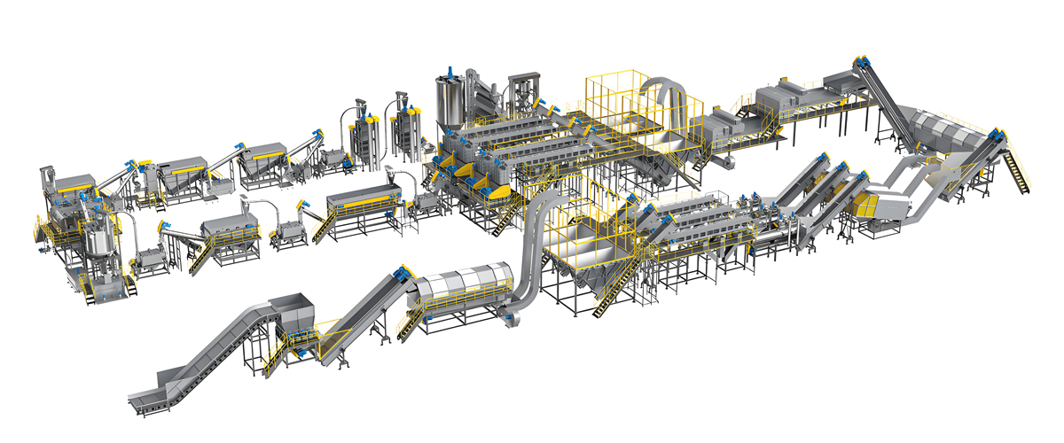
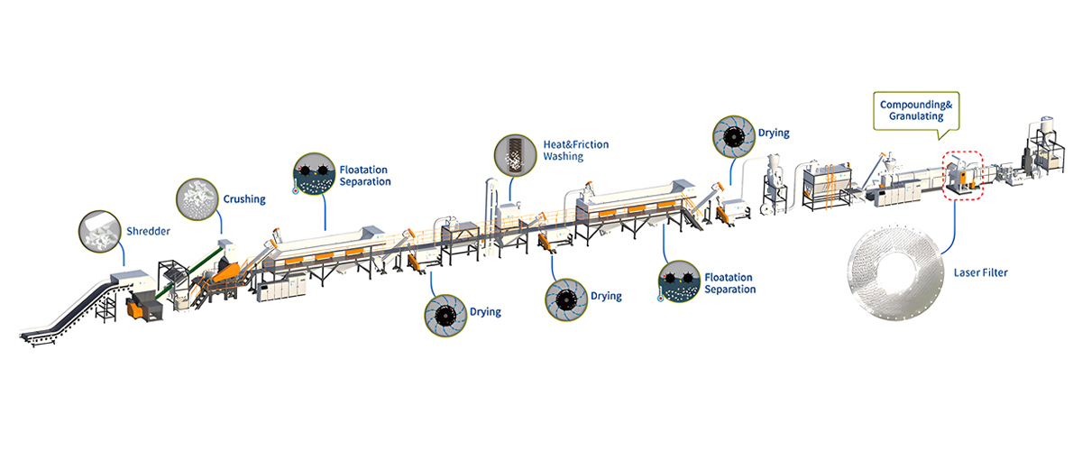
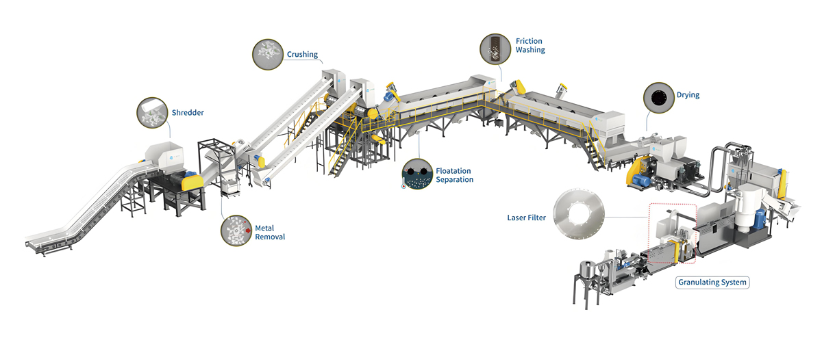
You cannot position detectors intelligently without a stage-by-stage map of the process and of the metal risk each stage carries. A modern post-consumer washing line — whether configured for food-grade PET bottles at 500 to 6,000 kg/h or for soft PP and PE film at 500 to 1,500 kg/h — follows a consistent sequence. The following walkthrough describes the standard Polyretec configuration and identifies the metal exposure at each step.
Stage 1: Bale Breaking and Infeed Conveying
Bales arrive strapped with steel or PET banding and are opened over a bale breaker or directly onto an inclined infeed conveyor. This is the dirtiest point in the entire plant from a tramp metal perspective. Steel baling wire, wire ties, nails, bottle caps with metal liners, aerosol cans, cutlery, coins, batteries and construction debris are all routinely found. Belt speed here is typically 0.2 to 0.4 m/s with a burden depth of 100 to 250 mm.
Stage 2: Manual Picking and Near-Infrared Sorting
A picking platform removes bulk contaminants, oversized items and non-target polymers. Near-infrared sorting units then separate by polymer type and, on many PET lines, by color. Near-infrared sensing identifies polymers by their reflectance spectrum and cannot see metal reliably — a metal object is simply classified as an unrecognized item, which may or may not trigger ejection depending on how the sorter is configured. Near-infrared sorting is therefore a complement to, never a substitute for, metal detection.
Stage 3: Shredding
A single-shaft or double-shaft shredder reduces whole bottles, film rolls or rigid parts to a 40 to 80 mm fraction. Shredders are relatively tolerant of metal because they run slowly at 20 to 100 rpm with high torque, but they are not immune: a hardened steel object can still jam the rotor, trip the drive on overload, or bend a fixed counter-knife. Worse, the shredder is itself a metal source — worn knife fragments, broken bolt heads and screen basket wear particles all enter the product stream downstream of every metal barrier placed upstream.
Stage 4: Pre-Wash and Label Removal
A pre-wash drum or trommel and a dedicated label remover strip sleeve labels, loose paper and surface dirt using mechanical friction and water sprays. Heavy metal items that survived earlier stages tend to settle here and can be recovered from the sludge trap, but light metal fragments — foil laminate, thin aluminum, wire — travel onward with the plastic.
Stage 5: Wet Crushing
The wet crusher, also called a wet granulator, reduces the material to 10 to 14 mm flake using a rotor running at 500 to 900 rpm with water injection for lubrication and simultaneous washing. This is the most metal-vulnerable machine in the entire line. Rotor and stator blades are made from D2, SKD-11 or H13 tool steel, hardened to 56 to 62 HRC, and the harder the steel the more brittle it is. A hardened tool steel edge striking a steel bolt at rotor tip speeds of 20 to 30 m/s will chip rather than deform.
Stage 6: Friction Washing
High-speed friction washers, running a paddle or auger shaft inside a perforated screen barrel, scrub the flake against itself and against the screen at 700 to 1,000 rpm. Metal fragments trapped between the auger flight and the screen act as a grinding medium — they score the flights, enlarge the perforations and generate their own secondary stainless steel contamination from the screen material itself.
Stage 7: Hot Caustic Washing
Hot washing is the chemical heart of a food-grade PET line. Flake is agitated in a heated vessel at 80 to 95 degrees Celsius with 1 to 3 percent sodium hydroxide solution and a surfactant, with a residence time of 10 to 20 minutes. The caustic saponifies adhesive residues, removes oils, hydrolyses the surface layer of contaminants and detaches remaining label glue. This is also a corrosive environment: carbon steel components anywhere in the hot wash circuit will corrode and shed iron oxide into the stream, which is why hot wash vessels, agitators and piping should be AISI 304 or 316 stainless throughout.
Stage 8: Rinsing and Sink-Float Separation
Multiple rinse tanks neutralize residual caustic and remove suspended fines. Sink-float separation then exploits density: in a plain water medium of approximately 1.0 g/cm³, PET at 1.33 to 1.38 g/cm³ sinks while PE at 0.91 to 0.96 g/cm³ and PP at 0.89 to 0.91 g/cm³ float. This step removes polyolefin caps and label fragments from a PET stream, or removes PET and PVC contamination from a polyolefin stream. Note carefully what it does to metal: aluminum at 2.70 g/cm³ and steel at 7.85 g/cm³ both sink, so a sink-float tank on a PET line concentrates metal into the product fraction rather than removing it.
Stage 9: Dewatering Centrifuge
A horizontal or vertical centrifuge spins residual surface water off the flake, taking moisture from roughly 15 to 20 percent down to 1 percent or below. The rotor runs at high speed inside a wedge-wire screen and is itself vulnerable to imbalance damage from dense metal fragments.
Stage 10: Thermal Drying
Hot air drying at 150 to 170 degrees Celsius in a pipe dryer, or a dryer plus buffer silo combination with a longer residence time, reduces moisture to 0.1 to 0.5 percent for flake sale, or considerably lower where the flake feeds a downstream extrusion stage without a vacuum vented barrel.
Stage 11: Air Classification and Dedusting
A zigzag air classifier or aspiration channel removes light fractions — residual label snippets, film shreds, dust — using controlled air velocity. Dense metal fragments are unaffected and continue with the product.
Stage 12: Product Silo and Bagging
Finished flake is conveyed to a storage silo, homogenized, and discharged to big bags or to the pelletizing feed system.
Stage-by-Stage Metal Risk Map
| Process Stage | Typical Metal Present | Material State | Damage Severity |
|---|---|---|---|
| Bale breaking / infeed conveyor | Baling wire, nails, cans, cutlery, coins | Dry, loose, 100-250 mm burden | Very High |
| Manual picking / near-infrared sorting | Missed small items, foil laminate | Dry, singulated | Medium |
| Shredder | Tramp metal plus own knife fragments | Dry, 40-80 mm fraction | High |
| Pre-wash and label remover | Fine wire, foil, bottle cap liners | Wet, high moisture | Medium |
| Wet crusher | Any surviving hard metal | Wet slurry, 10-14 mm flake | Very High |
| Friction washer | Metal fines, screen wear particles | Wet, agitated | High |
| Hot caustic washer | Corrosion products from carbon steel | Wet, 80-95 C, alkaline | Medium |
| Sink-float separation | Metal concentrates in sink fraction | Fully submerged | High for PET lines |
| Dewatering centrifuge | Dense fragments causing imbalance | Transitioning to damp | Medium |
| Thermal dryer and silo | Fine ferrous swarf from conveying | Dry, free-flowing, dusty | Medium, plus ignition risk |
| Pelletizing feed throat | Any residual fragment | Dry, metered feed | Very High |
The Metal Damage Chain: From Crusher Blades to Rejected Food-Grade rPET
Metal damage in a recycling plant propagates. A single event rarely stays contained at the machine where it occurred, and understanding the chain is what justifies the capital spend on a properly engineered detection package.
Link One: Crusher and Granulator Blade Fracture
Wet crusher blades are specified in D2 (a high-carbon high-chromium cold work tool steel), SKD-11 (the equivalent Japanese grade) or H13 (a hot work grade chosen where thermal shock from water injection is a concern). Hardness is typically 56 to 62 HRC for D2 and SKD-11, and 48 to 52 HRC for H13. This hardness is what gives 400 to 800 operating hours between regrinds on clean flake. It is also what makes the cutting edge brittle. When a hardened edge meets a mild steel bolt, the bolt deforms and the blade edge chips. A chipped blade produces oversized flake, raises motor current, unbalances the rotor and — because the rotor and stator gap is now inconsistent — accelerates wear on the remaining blades. One metal strike therefore usually means a full blade set change rather than a single blade change.
Link Two: Friction Washer Auger and Screen Wear
Friction washers depend on a tightly controlled clearance between the auger flight and the perforated screen — commonly 3 to 8 mm. A metal fragment lodged in that clearance behaves as a lapping tool. Flight edges round over, the clearance opens, washing efficiency falls, and the residual contamination level of the flake rises. Operators often misdiagnose this as a chemistry problem and increase caustic concentration or temperature, raising energy and chemical consumption for no benefit.
Link Three: Melt Filter Blinding and Screen Changer Duty
Where flake feeds an extrusion stage, the melt filter is the last physical barrier. Typical screen packs for recycling run 80 to 200 mesh, or 60 to 150 micron on a laser-drilled continuous screen changer. Metal fragments and the plastic char they generate blind screen area rapidly. Melt pressure before the screen rises, the screen changer indexes more often, each index causes a pressure and throughput transient that shows up as pellet size variation, and material consumption from purge losses climbs. A line that should change screens once per shift may end up changing every 40 minutes.
Link Four: Downstream Converter Failures
Metal that survives into the finished pellet becomes the converter’s problem, and therefore the recycler’s commercial problem. In injection molding, a hard inclusion blocks a nozzle tip or a hot runner gate, causing short shots and unplanned mold opening. In film extrusion, a 200 micron metal particle in a 20 micron blown film is a guaranteed bubble burst — an event that can cost hours of line restart and a full roll of scrap. In pipe extrusion, inclusions become stress concentrators that fail hydrostatic pressure testing.
Link Five: Dust Ignition Risk
The dry end of a washing line — pneumatic conveying lines, cyclone separators, the zigzag classifier, silo filling points — carries fine plastic dust in suspension. Suspended polyolefin and PET dust has a minimum ignition energy low enough that a mechanical or electrostatic spark can initiate combustion in the right concentration range. Ferrous and non-ferrous tramp metal striking rotating steel is a recognized ignition source. Removing metal before the dry conveying section is a control measure that belongs in the plant’s dust hazard assessment.
Link Six: Food-Grade Rejection
The commercial endpoint of the damage chain is outright rejection. Food-grade rPET buyers specify metal content and audit the supplier’s control system. A recycler that cannot show a documented metal critical control point, calibration records and traceability of rejected material will not pass a second-party audit, and will not hold a food-grade contract. This is the reason metal detection integration should be designed at the plant layout stage, not retrofitted after the first complaint.
Damage Chain Impact Summary
| Damage Link | Failure Mode | Typical Downtime | Relative Repair Cost | Preventing Barrier |
|---|---|---|---|---|
| Crusher blade chipping | Edge fracture, rotor imbalance, oversized flake | 6-10 h | High | Points 1 and 2 |
| Shredder knife or counter-knife damage | Rotor jam, drive overload trip | 3-8 h | Medium | Point 1 |
| Friction washer auger wear | Clearance loss, washing efficiency drop | Gradual, 12-24 h to rebuild | High | Points 1, 2 and 3 |
| Melt filter blinding | Pressure rise, frequent screen indexing, purge loss | Continuous yield loss | Medium, recurring | Points 4 and 5 |
| Screw and barrel scoring | Loss of melt pressure, output decay | 3-7 days for replacement | Premium | Point 5 |
| Converter nozzle or film failure | Short shots, film bursts, batch scrap | Customer-side | Very High, reputational | Points 4 and 5 |
| Dust ignition event | Deflagration in conveying duct or silo | Days to weeks | Very High | Points 1, 2 and 4 |
| Food-grade batch rejection | Full lot returned, contract at risk | Commercial | Very High | All five points plus records |
Six Metal Detection and Separation Technologies Explained
No single technology removes all metal from a plastic recycling stream. Ferrous, non-ferrous and austenitic stainless steel each respond to different physical principles, and the practical answer is a layered package in which each device covers the blind spot of the others. The six technologies below are the standard toolkit.
1. Inline Belt Metal Detector
A balanced-coil belt detector consists of a transmitter coil and two receiver coils wound around a rectangular aperture through which the conveyor belt passes. In the absence of metal the two receiver signals cancel. Any conductive or magnetically permeable object disturbs the balance, and the amplitude and phase of the disturbance identify the metal type. Modern units run multi-frequency, typically 40 kHz to 900 kHz, which allows the electronics to separate the product effect signal from the true metal signal.
Realistic sensitivity on a dry, evenly spread flake burden is ferrous spheres of 1.0 to 2.0 mm, non-ferrous spheres of 1.5 to 3.0 mm and SUS304 austenitic stainless spheres of 2.0 to 4.0 mm. The governing rule is that sensitivity degrades with aperture height: the detection field is weakest at the geometric center of the aperture, so a 300 mm high aperture will always outperform an 800 mm high aperture on the same electronics. Never over-specify aperture height for convenience — every additional 100 mm of aperture height costs measurable sensitivity.
Aperture Height Versus Achievable Sensitivity
| Aperture (W x H, mm) | Fe Sphere (mm) | Non-Fe Sphere (mm) | SUS304 Sphere (mm) | Typical Application Point |
|---|---|---|---|---|
| 300 x 150 | 0.8 – 1.0 | 1.0 – 1.5 | 1.5 – 2.0 | Dry flake, pelletizing feed |
| 500 x 250 | 1.0 – 1.5 | 1.5 – 2.0 | 2.0 – 2.5 | Post-shredder transfer belt |
| 800 x 400 | 1.5 – 2.0 | 2.0 – 3.0 | 3.0 – 4.0 | Bale infeed conveyor |
| 1200 x 500 | 2.0 – 3.0 | 3.0 – 4.5 | 4.0 – 6.0 | Wide bale-breaking conveyor |
2. Gravity Fall and Tunnel Metal Detector
A gravity fall detector is a circular or square coil assembly fitted into a vertical free-fall pipe, usually 50 to 200 mm bore. Material falls through the coil and any metal triggers a fast-acting pneumatic flap or a rotating reject gate mounted immediately below. Response time from detection to valve actuation is typically under 100 ms, which is what makes the technology viable on free-falling material moving at 3 to 6 m/s.
Gravity fall units suit dry, free-flowing flake and pellets, which makes them ideal at the dryer discharge, the silo inlet and the extruder feed throat. They are not suitable for wet, sticky or bridging material. Because the aperture is small, sensitivity is excellent — often 0.6 to 1.2 mm ferrous on a 100 mm bore. The reject flap must be sized so that the reject window captures the metal plus a defined quantity of surrounding product; a common setting is a 150 to 400 ms open window, deliberately generous, so that a fast-moving fragment cannot outrun the gate.
3. Overband Magnet (Suspended Magnetic Separator)
An overband magnet is a permanent or electromagnetic block suspended above a conveyor with its own self-cleaning belt running around it. Ferrous objects are lifted out of the burden, carried sideways by the cleaning belt and discharged into a collection bin. Field strength at the magnet face is typically 800 to 1,200 Gauss for a self-cleaning permanent unit, and installation height above the belt surface is critical: 200 to 350 mm from the magnet face to the top of the material burden for a standard duty unit.
Every extra 50 mm of suspension height reduces the effective lifting force substantially, because magnetic field strength falls off sharply with distance. The overband should be mounted either directly over the head pulley in cross-belt configuration or over the flat section of the belt in inline configuration. Cross-belt mounting is preferred where the burden is deep and irregular, as at bale breaking. Overband magnets handle only ferromagnetic material — they will not touch aluminum, copper, brass or austenitic stainless.
4. Grate Magnet and Magnetic Rod Assemblies
A grate magnet is a grid of neodymium iron boron rare-earth rods, typically 25 mm diameter on 50 mm centers, installed in a hopper outlet, chute or silo discharge. Surface field strength on a good rare-earth rod is 10,000 to 12,000 Gauss, which is an order of magnitude above an overband magnet, because the material contacts the rod directly rather than being lifted across an air gap.
The purpose of a grate magnet is entirely different from an overband: it captures fine ferrous swarf, wire fragments, weld spatter and rust particles in the 0.2 to 3 mm range that a belt detector would never see and an overband would never lift. Grate magnets are a housekeeping device and require manual or automatic cleaning on a fixed schedule — an uncleaned grate saturates and begins releasing captured particles back into the stream. Rare-earth material also loses field strength above its maximum service temperature, so grates installed after a 150 to 170 degree Celsius dryer must be specified with a high-temperature neodymium grade or, better, located where product temperature has dropped below 80 degrees Celsius.
5. Eddy Current Separator
An eddy current separator is the only practical bulk technology for removing non-ferrous metals — aluminum, copper, brass, zinc — from a plastic stream. A high-speed magnetic rotor, running at roughly 3,000 rpm inside a slower non-metallic shell, generates a rapidly alternating magnetic field at the discharge end of a conveyor. Conductive non-ferrous particles have eddy currents induced in them; those currents create an opposing field and the particle is physically repelled, throwing it further forward than the non-conductive plastic. A splitter plate positioned in the trajectory divides the two streams.
Effectiveness depends on the conductivity-to-density ratio: aluminum separates extremely well, copper and brass reasonably well, lead and austenitic stainless barely at all. Particle size matters — below roughly 3 to 5 mm the induced eddy current becomes too weak relative to particle mass, so an eddy current separator is best positioned on shredded material at 20 to 80 mm rather than on fine flake. Feed must be a thin, evenly spread monolayer; a piled burden dramatically reduces efficiency.
6. X-Ray Inspection
X-ray transmission imaging detects contaminants by density contrast rather than by conductivity or magnetic permeability. This gives it a unique capability: it identifies dense metal encapsulated inside a plastic object — a metal insert inside a rigid part, a battery inside a container, a metal spring inside a pump dispenser — that an inductive detector might miss because the surrounding plastic mass masks the signal, and that a magnet cannot reach because the metal is not exposed.
X-ray also detects stone, glass and ceramic, which no inductive or magnetic technology can. The trade-offs are capital cost, the requirement for radiation shielding and periodic radiation safety verification, and the need for a stable, evenly spread material presentation. X-ray is therefore normally justified only on high-value food-grade lines or where the feedstock is known to contain encapsulated metal.
Technology Selection Matrix
| Technology | Detects Fe | Detects Non-Fe | Detects SUS304 | Works on Wet Material | Removes or Only Alarms | Relative Investment |
|---|---|---|---|---|---|---|
| Inline belt metal detector | Yes, excellent | Yes, good | Yes, moderate | Yes, with compensation | Alarm plus belt stop or reject | Medium |
| Gravity fall detector | Yes, excellent | Yes, very good | Yes, good | No | Removes via reject flap | Low to Medium |
| Overband magnet | Yes, bulk removal | No | No | Yes | Removes continuously | Medium |
| Grate magnet (rare-earth) | Yes, fines only | No | Weakly magnetic grades only | Yes, but cleaning is harder | Removes, needs cleaning | Low |
| Eddy current separator | No, must be pre-removed | Yes, excellent for aluminum | Poor | Prefers dry | Removes continuously | High |
| X-ray inspection | Yes, including encapsulated | Yes | Yes | Yes | Alarm plus reject | Premium |
Established suppliers in this equipment segment include Sesotec, Eriez, Steinert, Mesutronic and Cassel Messtechnik, and Polyretec integrates units from several of these depending on the customer’s regional service preference and on whether the plant must comply with a specific retailer or brand-owner protocol. The integration engineering — mounting, timing, interlocks and validation — matters more than the brand badge on the control cabinet.
The Five-Point Detection Layout for a Washing Line
A layered metal control strategy places five barriers along the process. Each barrier has a distinct target, a distinct technology and a distinct failure consequence, and none of them is redundant. The following layout is the reference configuration Polyretec applies to food-grade PET bottle washing lines and to hard PP/PE crushing and washing lines, scaled to throughput.
Point 1: Infeed Conveyor — Overband Magnet Plus Belt Detector
The mission at Point 1 is to protect the shredder and to remove the bulk mass of tramp metal before it can fragment. Install a self-cleaning cross-belt overband magnet at 800 to 1,200 Gauss over the flat section of the infeed conveyor, with a face-to-burden clearance of 250 to 350 mm for a 200 mm deep burden. Immediately downstream, install a wide-aperture belt metal detector — typically 800 x 400 mm or 1,200 x 500 mm depending on belt width.
At this point the detector should be configured for belt stop plus audible and visual alarm rather than for automatic rejection. The reason is practical: the objects here are large and irregular, a reject flap cannot handle a 300 mm length of baling wire, and an operator on the picking platform can remove the item manually in seconds. Sensitivity is deliberately set coarse — a 3 to 5 mm ferrous equivalent — because the aim is to catch damaging objects, not fines, and a hair-trigger setting on a dirty infeed will stop the line continuously.
Point 2: Post-Shredder, Pre-Crusher — Second Magnetic Stage Plus Detection
The mission at Point 2 is to protect the wet crusher, the most expensive wear component in the line. Material here is 40 to 80 mm, still dry or only lightly wetted, and travelling on a transfer belt at 0.3 to 0.6 m/s. Install a drum magnet at the head pulley or a second overband unit, followed by a 500 x 250 mm belt detector set to a finer threshold — 1.5 to 2.0 mm ferrous equivalent.
This is the ideal position for an eddy current separator on lines processing mixed rigid waste, because the particle size band of 20 to 80 mm is exactly where eddy current efficiency peaks and because the material is still dry. Configure Point 2 for automatic reject via a pneumatic diverter or a reversing belt section rather than for line stop, since stopping a shredder mid-charge is disruptive.
Point 3: Post-Wet-Wash, Pre-Dewatering — Wet-Compensated Detection
Point 3 is the hardest installation in the plant and the one most often omitted. Material leaving the friction washers and hot wash vessels carries 15 to 25 percent free surface moisture with dissolved sodium hydroxide, making it markedly conductive. The product effect signal can be an order of magnitude larger than the signal from a 2 mm stainless sphere.
Three engineering measures make Point 3 viable. First, specify a multi-frequency detector with true phase compensation, and perform the product effect learning routine on genuinely wet production material rather than on a dry sample. Second, control the presentation: run the material as a thin, uniform layer on a dewatering screw discharge or a drainage belt rather than as a slug of slurry. Third, accept a realistic sensitivity target of 3 to 5 mm ferrous equivalent, and treat Point 3 as an interception barrier for medium fragments rather than as a fine-particle filter. Enclosure rating must be IP65 or better, with stainless housing and a washdown-compatible cable gland arrangement.
Point 4: Dryer Discharge and Silo Inlet — Grate Magnet Plus Gravity Fall Detector
Point 4 protects product quality and the dry conveying system, and it is where the plant achieves its best sensitivity because the material is dry, free-flowing and presented in a small aperture. Install a rare-earth grate magnet at 10,000 to 12,000 Gauss in the silo inlet chute to capture ferrous fines and swarf, and a gravity fall detector with a 100 to 200 mm bore in the vertical drop leg, with a pneumatic reject flap directly beneath.
Verify that product temperature at the grate is below the service limit of the magnet grade — standard neodymium iron boron loses coercivity above roughly 80 degrees Celsius, so if flake leaves a 150 to 170 degree Celsius dryer the grate belongs after a cooling section, or a samarium cobalt or high-temperature neodymium grade must be specified. Sensitivity here should be set to 1.0 to 1.5 mm ferrous, 1.5 to 2.5 mm non-ferrous, 2.0 to 3.0 mm SUS304.
Point 5: Pelletizing Feed Throat — The Last Line of Defense
Point 5 exists to protect the screw and barrel of the recycling extruder and to keep the melt filter clean. Install a small-aperture gravity fall detector — 50 to 100 mm bore is usually sufficient — in the drop between the metering feeder and the feed throat, or a compact belt detector on the feed conveyor where the extruder is fed by a weigh belt.
Set this detector to its maximum practical sensitivity, typically 0.8 to 1.2 mm ferrous, and interlock it to stop the feeder and raise a critical alarm rather than simply rejecting. At this position the volume of material involved is small, the value of the protected asset is very high, and a false stop is far cheaper than a scored barrel. Where the pelletizing island uses a twin-screw system such as a Kerke KTE-series machine, the feed-throat detector should also be interlocked with the side feeder and the loss-in-weight feeders so that the entire feed group halts together.
Five-Point Layout Specification Summary
| Point | Location | Equipment | Target Sensitivity (Fe) | Reaction Mode | Asset Protected |
|---|---|---|---|---|---|
| 1 | Bale infeed conveyor | Overband magnet 800-1200 Gs plus 800×400 belt detector | 3.0 – 5.0 mm | Belt stop plus alarm, manual removal | Shredder |
| 2 | Post-shredder transfer belt | Drum or overband magnet plus 500×250 detector, optional eddy current separator | 1.5 – 2.0 mm | Automatic diverter reject | Wet crusher, friction washer |
| 3 | Wet section discharge, pre-centrifuge | IP65 multi-frequency detector with phase compensation | 3.0 – 5.0 mm | Diverter reject plus alarm | Centrifuge, dryer |
| 4 | Dryer discharge and silo inlet | Rare-earth grate magnet 10000-12000 Gs plus gravity fall detector | 1.0 – 1.5 mm | Pneumatic flap reject under 100 ms | Product quality, conveying system |
| 5 | Pelletizing feed throat | Small-bore gravity fall detector 50-100 mm | 0.8 – 1.2 mm | Feeder stop, critical alarm | Screw, barrel, melt filter |
Integration, Interlocks and Reject Timing Engineering
A metal detector that alarms but does not act reliably on that alarm is decoration. The integration engineering — interlock logic, reject actuation timing, signal interfaces and alarm management — is where most retrofit projects fail, and it deserves as much attention as the choice of detector.
Interlock Architecture
Each detection point must be wired into the line control system with a defined reaction, and the reaction must be appropriate to the position. Three reaction classes cover almost all cases:
- Class A — Stop and hold. The conveyor or feeder stops, an upstream star feeder or rotary valve closes, and the line will not restart until an operator acknowledges and clears the fault. Used at Points 1 and 5.
- Class B — Reject and continue. A pneumatic diverter flap, air-blast nozzle or reversing belt segment removes a defined slug of material into a reject bin while the line continues running. Used at Points 2, 3 and 4.
- Class C — Alarm and log only. The event is recorded and the operator is notified, but no mechanical action is taken. Reserved for monitoring positions and for the commissioning period, never for a validated critical control point.
Reject Window Timing Calculation
The single most common commissioning error is a reject window that opens too late or closes too early, allowing the detected fragment to pass. The calculation is straightforward but must be done for every installation.
For a belt-mounted detector, the reject delay is the distance from the center of the detector coil to the reject device, divided by belt speed. Take a detector coil center 2.4 m upstream of a diverter flap on a belt running at 0.4 m/s: the delay is 2.4 divided by 0.4, or 6.0 seconds. The window duration must then cover the uncertainty in the detection position plus the physical length of the material slug to be removed. A practical rule is to open the flap for the time it takes 0.5 to 1.0 m of belt to pass — at 0.4 m/s, that is 1.25 to 2.5 seconds.
For a gravity fall detector, the material is accelerating under gravity and the timing is much tighter. A fragment detected at the coil and falling 0.5 m to the flap reaches it in approximately 0.32 seconds, arriving at about 3.1 m/s. This is why gravity fall systems demand valve response under 100 ms and why the flap should be mounted as close beneath the coil as mechanically possible. Always verify the calculated delay empirically during commissioning by dropping a marked test sphere and confirming it lands in the reject bin, then repeat at the highest and lowest expected line throughputs.
Reject Bin Management
The reject container must have a full-level detector — a capacitive or ultrasonic sensor is normal — interlocked to raise an alarm and, on food-grade lines, to stop production when full. The bin must be lockable or at least tamper-evident, because a validated critical control point requires that rejected material cannot be returned to the process without a documented decision. Rejected material is rarely pure metal; it is mostly good plastic with one fragment in it, so most plants run a secondary manual or small-scale re-sorting step to recover the plastic. That secondary stream must re-enter the process upstream of a detection point, never downstream.
Signal Interfaces and Control Integration
| Interface Type | Typical Signals Carried | Latency | When to Use |
|---|---|---|---|
| Hardwired digital output (relay or transistor) | Metal detected, fault, ready, reject confirm | Under 10 ms | Always, as the primary safety-relevant path |
| Profinet | Full status, sensitivity setpoint, event counter, diagnostics | 1 – 10 ms cycle | Siemens-based line control, preferred for new builds |
| Modbus TCP | Status, parameters, event log read-out | 10 – 100 ms | Mixed-brand plants, retrofits, data historian links |
| EtherNet/IP | Full status and configuration | 1 – 20 ms | Rockwell-based control architectures |
| Analog 4-20 mA | Raw signal amplitude for trend monitoring | Continuous | Optional, useful for drift diagnostics |
| Safety-rated circuit (dual-channel) | Emergency stop chain, guard interlocks | Under 10 ms | Where the interlock forms part of the machine safety function |
Best practice is a dual path: a hardwired digital output drives the physical stop or reject action, while the fieldbus link carries diagnostics, event counts and sensitivity settings to the line HMI and the plant data historian. Never rely on the fieldbus alone for the actuation path — a network fault must not silently disable metal rejection.
Alarm Grading and Reset Policy
Not every metal event deserves the same response. A sensible three-tier grading avoids alarm fatigue while preserving control:
- Level 1 (informational): a single detection event with successful automatic reject. Logged, counter incremented, no operator action required. Automatic reset.
- Level 2 (warning): three or more events within a defined window, for example 10 minutes, indicating a contaminated batch. Operator notified, supervisor informed, feedstock source flagged. Manual acknowledgment.
- Level 3 (critical): detector fault, reject valve failure confirmation missing, reject bin full, or a Point 5 detection. Line stops, manual reset only, event requires written record before restart.
Automatic reset should be permitted only for Level 1. On a food-grade line, every Level 2 and Level 3 event must generate a record with timestamp, detection point, sensitivity setting in force, batch identification and the disposition of the rejected material. This record set is what an auditor will ask to see.
False Reject Control
A detection system that rejects too much is abandoned by operators within weeks — they turn the sensitivity down or bypass it entirely, which is worse than having no detector. Target a false reject rate below 0.5 percent of material throughput at Points 2, 3 and 4. Achieving this requires correct product effect learning, stable belt tracking, mechanical isolation from vibration, and a reject window no longer than necessary. Monitor the ratio of reject mass to confirmed metal finds monthly; if the ratio is rising, investigate before an operator solves the problem informally.
Interference Factors and Engineering Countermeasures
Inductive metal detectors are sensitive instruments installed in one of the most electrically and mechanically hostile environments in the process industries. Understanding the interference mechanisms is what separates a system that holds 1.5 mm sensitivity for years from one that drifts to 6 mm within a month.
Product Effect
Product effect is any signal generated by the product itself rather than by a contaminant. In plastic recycling there are three main sources. Moisture and dissolved electrolytes — particularly residual sodium hydroxide from hot washing — make the material conductive, producing a signal in the same phase region as non-ferrous metal. Carbon black loading in recycled PE and PP, common in agricultural film, pipe regrind and automotive parts, makes the material partially conductive. And conductive mineral fillers or residual soil in post-consumer feedstock add a variable baseline.
The countermeasure is phase discrimination: the detector electronics identify the phase angle of the product signal and null it, leaving the metal signal visible. On multi-frequency units the system can operate at two or more frequencies simultaneously and compare responses, which greatly improves stainless steel detection in a conductive product. The critical practical point is that the learning routine must be run on real production material in its real state — running it on a clean dry sample and then processing wet caustic flake guarantees nuisance alarms.
Electromagnetic Interference from Drives
A washing line is full of variable frequency drives and servo drives — shredder, crusher, friction washers, centrifuge, blowers, conveyors. These generate broadband electrical noise through fast switching, and a detector coil is effectively an antenna. Countermeasures are cumulative: fit output filters or motor chokes on drives within 10 m of a detector head; route detector signal cables in a separate tray at least 300 mm from power cables and cross power runs at 90 degrees; use shielded, twisted-pair signal cable; and keep the detector power supply on a clean circuit, ideally through an isolating transformer.
Grounding and Shielding Discipline
Ground loops are the most common cause of unexplained sensitivity loss. Apply single-point grounding: the detector head, its control unit and the conveyor frame section within the detector’s clearance zone should all be bonded to a single ground point, not to multiple points that can carry circulating current. Cable shields should be terminated at one end only — normally the control unit end — to prevent the shield itself from becoming a current path. Verify ground resistance during commissioning and re-verify it after any electrical work on the line.
Mechanical Vibration
Vibration moves the coil relative to nearby metal, producing a modulated signal indistinguishable from a small contaminant. Shredders and crushers transmit substantial vibration through the building structure. Mount the detector on its own reinforced frame with anti-vibration isolators, not on the conveyor stringer of a machine that shakes. Verify that the belt does not touch the aperture at any point through its travel, and that belt tracking is stable — a belt that wanders and periodically contacts the aperture frame produces intermittent false triggers that are extremely difficult to diagnose.
Metal-Free Zone Around the Head
Every inductive detector requires a metal-free zone around the aperture. The working rule is that no moving metal, and no large static metal mass, should be within 1.5 times the aperture height in front of and behind the coil. For an 800 x 400 mm aperture, that means 600 mm of clearance on each side. Static metal within the zone can be tolerated if it is rigidly fixed and included in the calibration, but moving metal — a conveyor return roller, a chain drive, a pneumatic actuator, a passing forklift path — cannot. Non-metallic belt fasteners are mandatory: steel belt lacing passing through the aperture on every belt revolution is a classic commissioning failure.
Thermal Drift
Coil impedance changes with temperature, and a detector installed near a 150 to 170 degree Celsius dryer discharge or in an unheated warehouse with a 30 degree Celsius day-night swing will drift. Modern units include automatic temperature compensation, but the compensation range is finite. Keep detector heads out of direct thermal radiation, insulate hot chutes passing near a head, and allow a 15 to 30 minute warm-up after cold start before relying on calibrated sensitivity.
Interference Countermeasure Matrix
| Interference Source | Observable Symptom | Primary Countermeasure | Verification Method |
|---|---|---|---|
| Moisture and caustic residue | Continuous nuisance alarms on wet material | Multi-frequency phase compensation, relocate after centrifuge | Run 30 min of wet product with no test rod, count alarms |
| Carbon black filled PE or PP | Baseline shift when black material batch starts | Separate product memory profile per feedstock grade | Store and recall a recipe for each material type |
| Variable frequency drive noise | Alarms correlate with drive speed changes | Output filters, cable segregation, shielded twisted pair | Ramp each drive with product stopped, watch signal trace |
| Ground loop | Gradual sensitivity loss, mains-frequency noise | Single-point grounding, shield terminated one end only | Measure potential difference between frame ground points |
| Structural vibration | Random alarms with no product present | Independent frame, anti-vibration mounts | Run empty belt with crusher on and off, compare alarm rate |
| Moving metal in clearance zone | Periodic alarms at belt revolution interval | Enforce 1.5x aperture clearance, non-metallic belt fasteners | Physical survey plus empty-belt run of three revolutions |
| Thermal drift | Sensitivity varies between shifts or seasons | Thermal isolation, warm-up period, automatic compensation | Test rod check at shift start and shift end, compare |
Verification, Calibration and the Daily Test Routine
A metal detection system is only as good as its last verified test. Sensitivity drifts, coils age, belts wear, and operators adjust settings. A structured verification regime turns a piece of hardware into a defensible control.
Test Rod and Test Sphere Standards
Verification uses certified test pieces: spheres or rods of known diameter in ferrous carbon steel, non-ferrous (usually 316-free brass or aluminum for the non-ferrous check), and austenitic SUS304 stainless. Each test piece is embedded in a non-metallic carrier — a plastic card, rod or puck — so it can be placed accurately and recovered reliably. Test pieces must be certified for diameter and material, and should be inspected periodically for wear or damage; a scratched or corroded ferrous sphere gives a different response.
The Three-Position, Three-Height Test
The detection field inside an aperture is not uniform. It is strongest near the coil windings and weakest at the geometric center, and it can vary across the belt width. Verification must therefore test nine positions: left, center and right across the belt width, at low, middle and high positions in the aperture. In practice, on a belt detector the vertical dimension is tested by placing the test piece on the belt surface (low), on top of a representative product burden (high) and buried within the burden (middle).
The weakest point — almost always the geometric center of the aperture — defines the system sensitivity. A detector that finds a 1.5 mm sphere at the belt surface but misses it at mid-burden height has a real sensitivity worse than 1.5 mm, and the record must state the worst-case result, not the best.
Test Frequency
For a food-grade line operating a validated critical control point, test at the start of every shift and every four hours thereafter, plus after any of the following: sensitivity setting change, feedstock grade change, maintenance on the detector or conveyor, power interruption, or any Level 3 alarm. For non-food industrial lines, once per shift is normally adequate. Every test must be recorded — detection point, test piece sizes used, pass or fail at each of the nine positions, operator identity, sensitivity setting in force, and time.
Verification Schedule and Records
| Check | Frequency | Method | Pass Criterion | Record Retained |
|---|---|---|---|---|
| Sensitivity test, all three metal types | Shift start and every 4 h | Nine-position test piece pass | Detection at all nine positions | Signed log sheet or HMI record |
| Reject device function | Shift start | Test piece must land in reject bin | 100 percent capture, 3 of 3 trials | Log entry with trial count |
| Reject bin full sensor | Weekly | Manual actuation of sensor | Alarm raised, line reaction correct | Maintenance log |
| Grate magnet cleaning and inspection | Daily to weekly by loading | Withdraw, clean, weigh captured metal | Captured mass trended, no saturation | Capture log with mass |
| Overband magnet discharge check | Daily | Visual check of cleaning belt and bin | Belt running, bin not overfull | Shift checklist |
| Product effect re-learn | On every feedstock grade change | Run learning routine on live material | Stable baseline, no nuisance alarms in 30 min | Recipe stored under grade name |
| Full system validation | Annual, plus after major modification | Full nine-position test at all points, timing re-verification | All points meet specified sensitivity | Validation report |
Failure Response and Product Traceability
If a scheduled test fails, the material processed since the last successful test is suspect. The response protocol must be written before it is needed: stop the line, quarantine and clearly identify all product produced since the last passing test, investigate and correct the cause, re-test to a passing result, and then make a documented disposition decision on the quarantined material — reprocess, downgrade or discard. This is why test frequency matters commercially as much as technically: a four-hour interval limits the quarantine window to four hours of production, while a once-per-week test could put a week of output at risk.
Standards, Food-Contact Compliance and Machine Safety
Metal detection in a plastic recycling washing line sits at the intersection of three regulatory domains: food safety management, food-contact material regulation, and machinery and control system safety. Each imposes distinct obligations.
Food Safety Management and Critical Control Points
Under a HACCP framework, physical contamination by metal is a recognized hazard, and a metal detector with an automatic reject and a verification regime is the textbook example of a critical control point. Establishing metal detection as a CCP requires four elements: a defined critical limit (the sensitivity specification), a monitoring procedure (the test rod routine and its frequency), a corrective action procedure (the quarantine and disposition protocol), and verification and record-keeping. ISO 22000 provides the management system framework within which the HACCP plan operates, and BRCGS Packaging Materials sets out the specific expectations that packaging converters and their recycled-material suppliers are audited against, including the requirement for documented detection performance and reject-device failure detection.
Food-Contact Recycled Plastic Regulation
In the European Union, Regulation EU 2022/1616 governs recycled plastic materials and articles intended to come into contact with food. It requires that recycling processes be authorized, that the decontamination efficiency of the process be demonstrated, and that operators maintain a quality assurance system covering input material control and process monitoring. EFSA challenge testing is the mechanism by which decontamination efficiency is demonstrated: surrogate contaminants are deliberately introduced and their removal through the process is quantified. While challenge testing focuses on chemical migration rather than physical metal, the quality assurance system that surrounds it explicitly covers physical contamination control, and metal detection records form part of the evidence pack.
In China, GB 4806.7 sets the requirements for plastic materials and articles in contact with food, and recyclers supplying that market must be able to demonstrate equivalent input and process controls. In practice, a recycler exporting to multiple regions builds one control system that satisfies the strictest applicable requirement rather than maintaining parallel systems.
Machinery Safety and Control System Integrity
ISO 12100 sets the general principles for machinery risk assessment and risk reduction, and it is the correct starting point for a washing line safety file. Where a metal detector interlock forms part of a safety function — for example, stopping a conveyor to allow an operator to remove a detected object — the interlock must be designed to the required performance level determined by the risk assessment, with appropriate diagnostic coverage and, where necessary, dual-channel architecture. Simply wiring a detector relay into a motor contactor coil is not a safety function; it is a process interlock, and the distinction must be made explicit in the documentation.
Where the detection system is networked for diagnostics and remote monitoring, IEC 62443 provides the framework for industrial control system cybersecurity. The practical requirements are modest but important: segment the process network from the office network, control remote access to detector configuration, and ensure that sensitivity settings cannot be altered without authentication and an audit trail. A detector whose sensitivity can be changed by anyone with network access is not a validated control.
Standards Mapping for a Recycling Washing Line
| Standard or Regulation | Domain | Relevance to Metal Detection | Evidence Typically Required |
|---|---|---|---|
| HACCP | Food safety hazard analysis | Metal detection defined as a critical control point | Hazard analysis, CCP decision tree, critical limits |
| ISO 22000 | Food safety management system | Management framework wrapping the HACCP plan | Documented procedures, internal audit, management review |
| BRCGS Packaging Materials | Packaging supply chain audit scheme | Prescribes detection performance and reject failure detection | Test records, calibration certificates, failure protocol |
| EU 2022/1616 | Recycled plastic for food contact | Requires quality assurance covering input and process control | Process authorization dossier, monitoring records |
| EFSA challenge test | Decontamination efficiency | Establishes process capability; QA system includes physical control | Challenge test report, process parameter limits |
| GB 4806.7 | Food-contact plastics, China | Input control and contamination limits for the domestic market | Test reports, supplier declarations |
| ISO 12100 | Machinery safety risk assessment | Determines whether an interlock is a safety function | Risk assessment file, residual risk statement |
| IEC 62443 | Industrial control system security | Protects sensitivity settings and remote access | Network segmentation plan, access control records |
Specifying a Detection Package with Polyretec
Metal detection integration is easiest and cheapest when it is designed into the washing line at the layout stage. Retrofitting a detector into an existing line frequently means moving conveyors to create the required metal-free clearance zone, adding a drop leg to accommodate a gravity fall unit, or re-routing power cabling that was never planned with signal segregation in mind.
Polyretec, a Wanplas factory with origins in 2010 and brand establishment in 2017, builds food-grade PET bottle washing lines from 500 to 6,000 kg/h and PP/PE soft plastic crushing and washing lines from 500 to 1,500 kg/h, and specifies the metal detection package as part of the process design rather than as a bolt-on. The design approach combines Austrian process technology with Chinese manufacturing capability, and the same philosophy applies to the detection package: European-standard sensing and interlock engineering delivered at a competitive total installed cost. With more than 100 completed projects, service coverage in over 50 countries and a team of more than 24 engineers available for commissioning support, the integration work is treated as a deliverable, not as a customer responsibility.
Information Required to Specify the Package
A meaningful detection specification requires the following inputs, and a supplier who quotes without asking for them is quoting a catalog item rather than engineering a solution:
- Feedstock type and origin — post-consumer bottle bales, post-industrial rigid regrind, agricultural film, or mixed municipal stream — and the known metal contamination profile of that source.
- Throughput in kg/h at each detection point, and the bulk density and burden depth on each conveyor.
- End application of the recycled material: food-contact rPET, non-food packaging, pipe, fiber, or general-purpose regrind. This sets the sensitivity target.
- Whether the line discharges as washed flake or feeds directly into a pelletizing island.
- Belt widths, belt speeds and available straight-run length at each candidate mounting position.
- Existing control system platform and preferred fieldbus protocol.
- Local supply voltage, frequency, and any applicable regional certification requirement.
- Which audit schemes the plant is certified to or intends to certify to.
Commissioning Deliverables Checklist
| Deliverable | What It Must Contain | Who Signs Off |
|---|---|---|
| Detection point layout drawing | All five points marked with clearance zones dimensioned | Process engineer and plant manager |
| Sensitivity specification sheet | Target Fe, non-Fe and SUS304 values per point, per material grade | Quality manager |
| Interlock and reject logic description | Reaction class per point, delay and window times, alarm grading | Controls engineer |
| Timing verification record | Measured reject capture at minimum and maximum throughput | Commissioning engineer |
| Product effect recipe set | One stored profile per feedstock grade, learned on live material | Process engineer |
| Test piece kit and log templates | Certified Fe, non-Fe, SUS304 pieces plus nine-position log sheet | Quality manager |
| Operator and maintenance training | Test routine, recipe selection, failure protocol, magnet cleaning | Production supervisor |
| Spare parts list | Reject valve seals, solenoids, sensor cables, test pieces | Maintenance manager |
Across the Wanplas brand, all factories share a common set of after-sales commitments, including an annual free spare parts allowance, free replacement of parts that fail within warranty, an open factory policy for customer inspection visits, and a production capacity guarantee written into the supply contract. For metal detection specifically, the practical value of that arrangement is in the consumables: reject valve seals, solenoid coils and certified test pieces are exactly the low-value, high-consequence items that plants forget to stock, and covering them under a standing allowance keeps the control system verified rather than quietly bypassed.
It is also worth noting how the detection package interacts with the rest of the recycling island. Where washed flake feeds a pelletizing line, the Point 5 detector should be commissioned together with the extruder feed group, and the melt filter or continuous screen changer specification should be reviewed at the same time — the two systems share the same protective purpose. Wanplas’s Kerke factory supplies twin-screw compounding extruders and single-screw recycling extruders that integrate with Polyretec washing systems, and coordinating the metal detection interlock with the extruder control system during a single commissioning visit avoids the classic situation where two suppliers each assume the other has handled the interface.
Frequently Asked Questions
How many metal detectors does a plastic recycling washing line really need?
A properly engineered line uses five detection or separation points rather than one: the bale infeed conveyor, the post-shredder transfer, the wet section discharge, the dryer and silo inlet, and the pelletizing feed throat. Each point protects a different asset with a different technology, and each covers a blind spot of the others. A single detector, wherever placed, either misses fine contamination (if placed early on a wide belt) or allows expensive machines upstream to be damaged (if placed late).
Can a metal detector replace an overband magnet, or vice versa?
No. They perform different functions. An overband magnet physically removes bulk ferrous material continuously without stopping the line, but it cannot touch aluminum, copper or austenitic stainless. A metal detector senses all three metal classes but does not remove anything by itself — it triggers a stop or a reject device. On the infeed conveyor the correct configuration is a magnet followed by a detector, so the magnet strips the bulk ferrous load and the detector catches what remains.
Why does wet material reduce metal detector sensitivity so severely?
Free surface water carrying dissolved sodium hydroxide from the hot wash stage is electrically conductive, so it induces eddy currents in the detector field just as a non-ferrous metal particle would. This is product effect. The detector electronics must null this signal using phase discrimination, and the larger the product signal, the less headroom remains for the genuine metal signal. Sensitivity at a wet position is realistically 2 to 3 times coarser than at an equivalent dry position, which is why the highest-sensitivity detection point in any washing line is after the dewatering centrifuge and dryer, not before.
What sensitivity should I specify for food-grade rPET flake?
At the dry detection point (silo inlet), a reasonable and achievable specification is 1.0 to 1.5 mm ferrous, 1.5 to 2.5 mm non-ferrous and 2.0 to 3.0 mm SUS304, verified at all nine test positions. At the pelletizing feed throat, where the aperture is small, 0.8 to 1.2 mm ferrous is attainable. Do not accept a supplier’s headline sensitivity figure without confirming the aperture size, the product state and the test position it refers to.
Why is austenitic stainless steel harder to detect than carbon steel?
Carbon steel is ferromagnetic, so it produces a large signal through magnetic permeability in addition to its conductivity signal. Austenitic grades such as SUS304 are essentially non-magnetic in the annealed condition and have relatively low electrical conductivity, so they produce only a small conductive signal whose phase sits close to that of moist product. This combination makes them the hardest common contaminant to find, and it is why stainless sensitivity is always specified separately and always a larger number than ferrous sensitivity.
How do I calculate the reject delay for a belt-mounted detector?
Divide the distance from the detector coil center to the reject device by the belt speed. A 2.4 m distance at 0.4 m/s gives a 6.0 second delay. Then set the reject window to cover the length of material you want removed — commonly 0.5 to 1.0 m of belt, which at 0.4 m/s is 1.25 to 2.5 seconds. Always verify empirically by dropping a marked test piece and confirming capture, and repeat the verification at both minimum and maximum production speeds because most washing line conveyors are inverter-driven and their speed changes with load.
What is the metal-free zone and how big must it be?
The metal-free zone is the volume around the detector aperture in which no moving metal and no significant static metal mass may be present. The working rule is 1.5 times the aperture height in front of and behind the coil. For an 800 x 400 mm aperture that is 600 mm of clearance each side. Common violations are steel belt lacing, return rollers positioned too close, pneumatic actuator bodies, handrails, and forklift traffic routes passing beside the head.
How often should the detection system be tested with test pieces?
For a food-grade line running a validated critical control point, test at the start of each shift and every four hours thereafter, plus after any sensitivity change, feedstock grade change, maintenance intervention, power interruption or critical alarm. For general industrial recycling, once per shift is usually sufficient. The test interval directly defines the quarantine window if a test ever fails, so a shorter interval is a form of insurance.
What happens to the rejected material?
Rejected material is mostly good plastic containing one contaminant, so most plants collect it in a monitored bin and run a secondary manual or small-scale sorting step to recover the plastic. Two rules apply: the reject bin must have a full-level sensor interlocked to alarm and stop production, and recovered material must re-enter the process upstream of a detection point so that it passes a barrier again. Returning recovered material downstream of the last detector defeats the entire control system and will be flagged immediately in an audit.
Can an eddy current separator remove stainless steel?
Only poorly. Eddy current separation depends on the ratio of electrical conductivity to density. Aluminum has a very favorable ratio and separates well. Copper and brass separate acceptably. Austenitic stainless steel has low conductivity and high density, giving a very poor ratio, so it is barely deflected. Stainless removal relies on inductive detection with a reject device, or on X-ray inspection, not on eddy current separation.
Does near-infrared sorting detect metal?
No, not reliably. Near-infrared sensing identifies polymers by their reflectance spectrum in the near-infrared band. A metal object returns a spectrum that does not match any polymer signature, so the sorter classifies it as unrecognized. Depending on configuration, unrecognized items may be ejected or may simply pass to the default output. Near-infrared sorting is a polymer separation technology and must never be counted as a metal control in a hazard analysis.
Why do we need a grate magnet if we already have a metal detector at the same point?
They catch different things. A grate magnet with rare-earth rods at 10,000 to 12,000 Gauss captures fine ferrous swarf, rust flakes and wire fragments down to a few tenths of a millimeter — particles far below the detection threshold of any inductive detector at a practical aperture size. The detector catches larger discrete fragments including non-ferrous and stainless. Neither substitutes for the other, and at the silo inlet both belong in series.
Will a metal detector interlock stop my whole washing line every time it alarms?
It should not, and it must not, or operators will bypass it. Only Point 1 (belt stop for manual removal of large objects) and Point 5 (feeder stop to protect the screw and barrel) should stop equipment. Points 2, 3 and 4 should use automatic reject and continue running. The alarm grading system — informational, warning, critical — is what keeps the number of production interruptions to a level operators will accept while preserving genuine control.
How do variable frequency drives affect metal detection?
Variable frequency drives switch at high frequency and radiate broadband electrical noise that couples into the detector coil and its signal cabling, raising the noise floor and reducing usable sensitivity. Countermeasures are output filters or motor chokes on drives within about 10 m of a head, physical segregation of signal and power cable routes by at least 300 mm with crossings at 90 degrees, shielded twisted-pair signal cable with the shield grounded at one end only, and a clean, ideally isolated power supply for the detector electronics.
Is X-ray inspection worth the investment for a plastic recycling line?
It depends on the feedstock and the end market. X-ray is the only technology that finds metal encapsulated inside a plastic body, and the only one that also detects stone, glass and ceramic. On a food-grade rPET line supplying brand owners with strict physical contamination specifications, or on a stream known to contain pump dispensers, metal inserts or battery-containing items, it can be justified. On a general polyolefin film washing line producing material for refuse sacks or pipe, the layered magnet-plus-inductive-detector package delivers the necessary protection at a far lower investment level.
Should the metal detector be included in the machine safety risk assessment?
Yes. Under ISO 12100 the risk assessment must consider the hazards associated with clearing detected objects — an operator reaching into a conveyor, a nip point at a diverter flap, stored pneumatic energy in a reject actuator. Where the interlock forms part of the protective measure, it must be engineered to the performance level the assessment demands, not simply wired as a process interlock. The distinction between a process interlock and a safety function must be stated explicitly in the documentation.
Conclusion
Integrating metal detection into a plastic recycling washing line is a layered systems problem, not a single equipment purchase. The physics dictate the architecture: ferrous, non-ferrous and austenitic stainless respond to different principles, wet material and dry material impose radically different sensitivity limits, and no single device at a single position can protect both the shredder at the front of the line and the extruder screw at the back. The five-point layout — overband magnet plus coarse belt detector at the infeed, magnetic separation plus finer detection after the shredder, wet-compensated detection before dewatering, rare-earth grate magnet plus gravity fall detection at the silo inlet, and a high-sensitivity detector at the pelletizing feed throat — addresses each risk at the point where it is technically easiest and economically most valuable to address.
What determines whether that architecture actually works is the integration engineering: reject delays calculated and verified at real production speeds, interlocks graded so that operators are not driven to bypass the system, cable routing and grounding executed with the discipline the physics requires, product effect learned on live wet material rather than a clean sample, and a nine-position test rod routine performed and recorded every four hours. These are unglamorous details, and they are precisely the details that separate a plant holding a food-grade contract from one selling into the commodity segment.
For recyclers planning a new line in 2026 or upgrading an existing one, the practical recommendation is to specify the detection package at the process layout stage, where clearance zones, drop legs and cable routes can be designed in at negligible extra cost, rather than retrofitting after the first blade failure or the first rejected shipment. Polyretec, a Wanplas factory with more than a decade of washing and pelletizing line experience across 50-plus countries, engineers the detection layout, interlock logic and verification protocol as part of the line design, and coordinates the pelletizing-side interface with Wanplas’s Kerke factory where a downstream extrusion stage is involved. Share your feedstock profile, target throughput and end-market specification, and the engineering team will return a five-point layout drawing with sensitivity targets, reaction classes and a commissioning validation plan for your specific line.