
A laser filter clogging event on a plastic recycling washing and pelletizing line is rarely a filter problem in isolation. It is the visible symptom of everything that happened upstream: how clean the flake was when it left the friction washer, how much moisture survived the centrifuge and dryer, how consistently the extruder held temperature, and whether the incoming bale actually matched the material specification the line was built for. The laser filter, with its drilled steel disc, rotating scraper and continuous discharge screw, is the most forgiving filtration technology available for post-consumer polyolefin because it removes contaminant without ever stopping the line. But that very forgiveness hides the root cause. A conventional screen changer forces a stop and a visible screen that tells you exactly what came through; a laser filter keeps running while the differential pressure climbs, the melt temperature creeps upward and the pellet quality drifts, and by the time the alarm trips the disc may already be plugged from the bore outward. Polyretec, a Wanplas factory specializing in plastic recycling equipment, builds washing lines, squeezer and dewatering systems and cutter-compactor pelletizing lines that depend on reliable laser filtration, and the most common support question from operators is not how the filter works but how to stop it from clogging in the first place. This guide treats laser filter clogging as a system-diagnosis discipline rather than a component replacement. It explains the working principle, publishes the pressure differential logic operators should live by, lays out sixteen distinct root causes with their diagnostic signatures and countermeasures, walks through a step-by-step diagnostic SOP, compares disc regeneration methods, and closes with the preventive program, the slag-analysis method, the link between clogging and pellet quality, the maintenance calendar and the safety envelope. The objective is that the next time a differential alarm appears, the response is a calibrated diagnosis, not a guessed change of settings.
What a Laser Filter Does in a Plastic Linha de Reciclagem
The laser filter is the final cleanliness gate between the molten recyclate and the pelletizing die. Its job is to strip out everything that should not become a pellet: paper fibre, sand, wood, metal fines, cross-linked char, unmelted high-melt-point polymer, gel and filler agglomerates. In a mature recycling line the laser filter is not a luxury stage added at the end; it is the component that permits the line to run continuously on dirty post-consumer feed without an operator standing by to swap screens. The penalty for that capability is that the filter’s health is expressed only through pressure signals, which means an operator who reads only the alarm light will almost always be reacting late.
Understanding the role requires separating two ideas that are often confused. The first is contaminant removal, which is a function of pore size. The second is contaminant handling, which is a function of the scraper and discharge system. A small pore size removes more, but it also clogs faster and raises pressure, so the discipline of laser filter operation is to choose the coarsest pore that still delivers the pellet quality the customer requires, then to keep that pore open by managing the upstream load. A line running 150 micrometre filtration on clean post-industrial regrind may run for days with almost no discharge; the same disc on mixed post-consumer film with paper and sand can fill its discharge bin within a shift. The filter has not changed. The feedstock has.
The reason this matters for troubleshooting is that clogging is almost always a feedstock-and-front-end story with a filtration symptom. When a laser filter clogs, the instinct is to open it, clean it and restart. That sequence restores production for a few hours and then the differential climbs again, because the cause, whether poor washing, wet flake, thermal degradation or a wrong pore size, is still producing contaminant faster than the scraper can clear it. The troubleshooting method in this article is built to break that loop by forcing a diagnosis before any intervention.
How a Laser Filter Works: Drilled Disc, Scraper and Discharge Screw
The heart of the device is a solid steel filter disc, not a woven mesh. A laser drills thousands of precisely tapered holes straight through the metal, and the available standard pore diameters are 70, 80, 100, 120 and 150 micrometres. The taper is the key anti-clog feature: the inlet side of each hole is larger than the outlet side, so contaminant that is larger than the throat cannot wedge deeply and the flow accelerates through the constriction rather than stagnating. This conical geometry is fundamentally different from a flat screen, where a particle sitting on the surface can bridge neighbouring openings and build a mat in seconds.
Molten polymer is forced from the inlet side of the disc to the outlet side by the pressure of the extruder and, on most lines, by a melt pump that sits immediately downstream. As the melt crosses the disc, solid contaminant is trapped against the inlet face. A scraper blade mounted on a slowly rotating carrier sweeps that face continuously, lifting the accumulated contaminant off the surface and pushing it toward a discharge port. The scraper speed is variable, typically 0.5 to 5 rpm, and is normally controlled to hold the differential pressure at a setpoint rather than run at a fixed rate. When the contaminant load is low, the scraper crawls; when the load spikes, the control system speeds it up.
The removed contaminant drops into a discharge screw, sometimes called an auger or a discharge auger, which transports it out of the melt chamber against the internal pressure. Because the discharge is continuous and mechanically sealed, the line never has to stop to clear contaminant. The volume of slag removed is the single most useful real-time indicator of filter load: on clean feed it is 0.5 to 3 percent of throughput, while on heavily contaminated feed it climbs to 5 to 8 percent. A sudden rise in discharge volume is the earliest honest signal that something upstream has changed, long before the differential alarm trips.
What the continuous system cannot do is reopen a pore that has been plugged from inside. The scraper only works on the face. If a particle is driven into the conical bore and lodges there, or if carbon from thermal degradation bakes onto the bore wall and shrinks the throat, no amount of scraping restores flow; only a thermal or mechanical regeneration of the disc does. This distinction, surface contamination versus bore plugging, is the hinge of the entire troubleshooting logic, because the two failure modes require completely different corrective actions.
Laser Filter Versus Alterador de Tela and Backflush Filtration
Before diagnosing a laser filter, it helps to know what the alternatives do, because several recycling lines run a laser filter in series with a conventional screen changer, and confusing the two leads to wrong conclusions. The table below compares the three technologies on the parameters that matter for a post-consumer recycling operation.
| Parâmetro | Laser Filter (disc plus scraper plus discharge screw) | Continuous Alterador de Tela (double-piston backflush) | Mesh Alterador de Tela (manual or hydraulic swap) |
|---|---|---|---|
| Line stop to change medium | None, continuous discharge | None, automatic indexing | Yes, every screen fill |
| Operator intervention | Very Low | Low to Medium | High |
| Typical fineness range | 70 to 150 micrometres | 80 to 250 micrometres | 100 to 600 micrometres |
| Handling of paper and fibre | Very Good, discharged continuously | Medium, fibre mats and blinds backflush | Poor, mats fast |
| Handling of sand and metal fines | Good, abrasive to scraper | Good, but wears seals | Medium |
| Consumable cost | Low, disc regenerated many times | Medium, screens consumed | Medium to High, screens consumed |
| Pressure stability | Good with control; rises on bore plugging | Good with backflush timing | Pulsing as screen loads |
| Best fit in a washing line | Heavy post-consumer contamination | Cleaner post-industrial streams | Low-spec rigid regrind |
| Relative capital cost | High | Medium to High | Low |
The practical conclusion is that a laser filter is the right tool for the dirty end of the recycling market, but it is not magical. On a line that also carries a continuous screen changer, the laser filter usually plays the coarse, continuous-discharge role and the screen changer plays the fine polishing role, and a clog that appears at the laser stage frequently originates at the screen stage when that upstream element has partially blinded and created a串联 bottleneck. Troubleshooting must therefore always ask which stage is the true bottleneck, not merely which stage tripped the alarm.
Where the Laser Filter Sits in the Washing and Pelletizing Process Chain
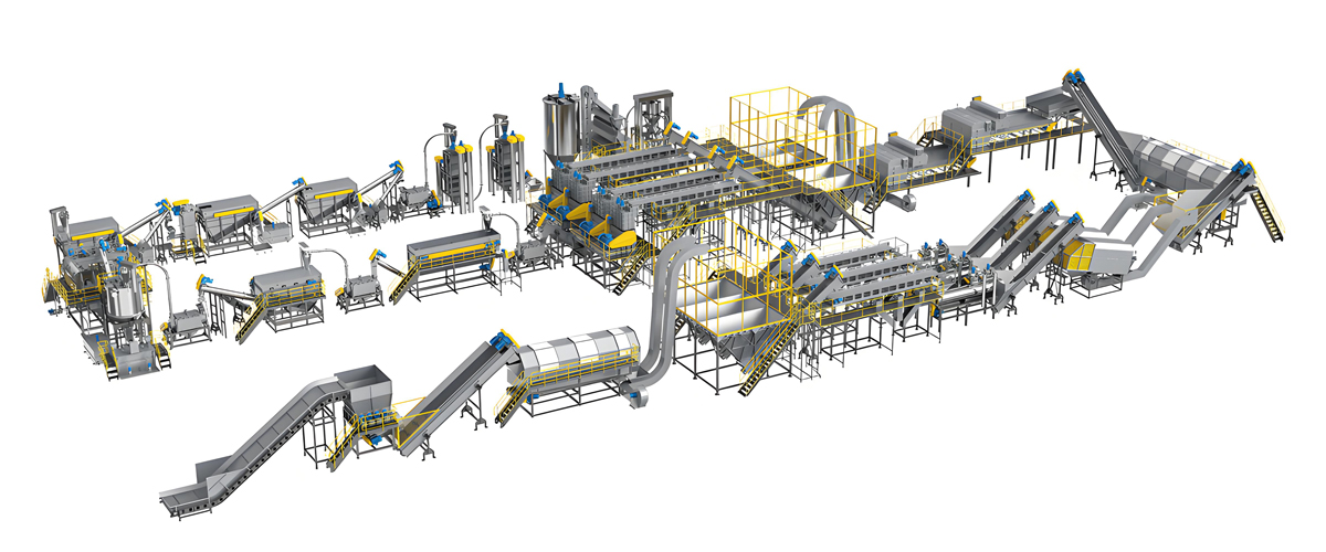
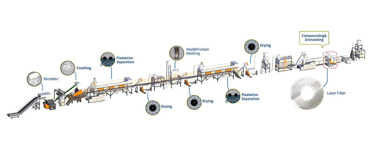
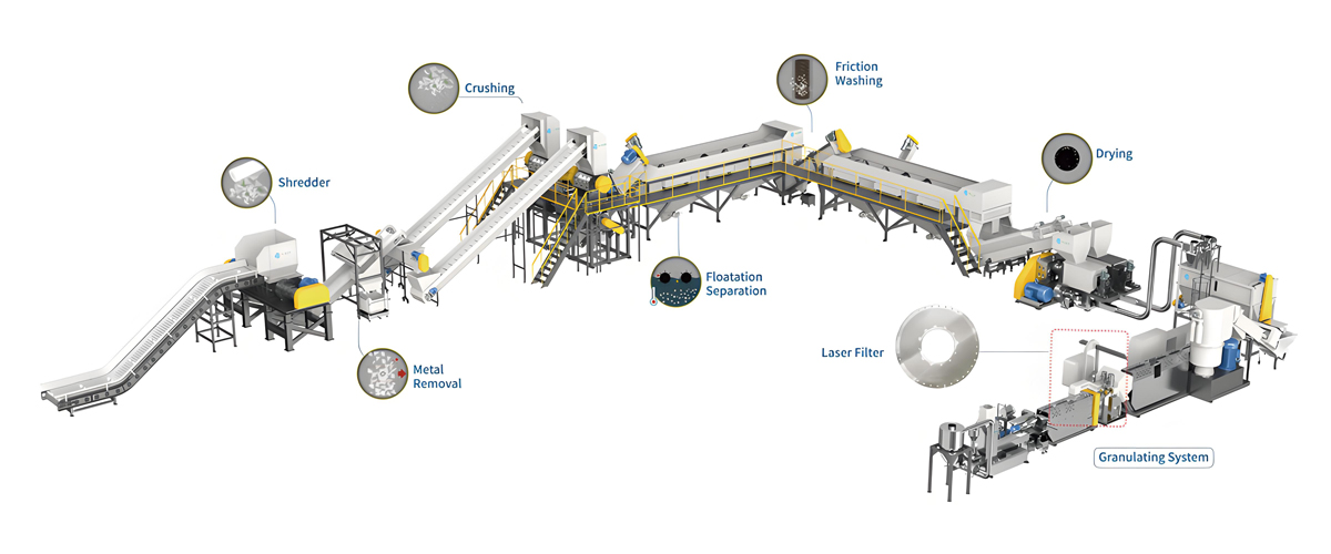
Clogging cannot be understood without the full chain in view, because every upstream stage feeds the filter. A complete post-consumer polyolefin recycling and pelletizing line runs roughly in this order: prewash to knock off loose dirt, coarse crushing or shredding to flake size, friction washer to mechanically scrub adhered soil, hot wash at about 90 degrees Celsius with 1 to 2 percent caustic (sodium hydroxide) to release labels and organics, cold rinse to remove the caustic and loosened soil, centrifugal dewatering, thermal or mechanical drying to drive residual moisture down, and finally extrusion and pelletizing. The laser filter lives at the end of that chain, mounted between the extruder and the melt pump or die head.
Seen this way, the laser filter is the receiving end of a long quality relay. If the friction washer loses pressure, if the hot wash temperature drifts below 90 degrees Celsius, if the caustic concentration falls outside the 1 to 2 percent window, if the rinse is short, or if the dryer cannot reach the target moisture, every one of those failures arrives at the filter as contaminant it must catch. The filter has no way to reject that load; it can only accumulate it. So a clogged filter is frequently the cumulative report card of the washing section, and the diagnostic SOP later in this article deliberately works backward from the filter to the washing stages.
It is also worth stating where the filter is not. It is not in the dry washing section, and it is not a substitute for good sorting. Material that is mis-sorted at the bale stage, for example a load that contains more PET, PA or PVC than the line was specified for, cannot be corrected by the filter; the foreign polymer either melts at a different temperature and forms gel or char, or it does not melt and plugs the pores. The filter manages contaminant that is already in the melt; it does not manage material identity. That boundary defines the difference between a cleaning problem and a feedstock problem, a distinction the root-cause table makes explicit.
Key Operating Parameters and the Pressure-Differential Alarm Logic
Reliable troubleshooting depends on knowing the normal numbers, because the differential pressure is the one signal operators can read continuously. The table below lists the values a well-tuned polyethylene recycling line should hold at the laser filter. These are engineering reference values; the actual setpoints on a specific machine are found on the nameplate and the commissioning report, and deviations from those should be the starting point of any investigation.
| Parâmetro | Normal Range | Alarm and Action Limit |
|---|---|---|
| Inlet melt pressure | 80 to 180 bar | Sustained above 180 bar indicates upstream restriction |
| Outlet (pump side) pressure | 40 to 100 bar | Below 40 bar suggests pump or downstream leak |
| Differential pressure across disc | 30 to 70 bar | Alarm above 100 bar; stop above 140 bar |
| Scraper speed | 0.5 to 5 rpm (variable frequency) | Pinned at maximum suggests chronic load |
| Discharge as share of output | 0.5 to 3 percent | 5 to 8 percent on high contamination; above 8 percent is abnormal |
| Melt temperature through disc | 200 to 250 degrees Celsius for PE | Below band raises viscosity and pressure; above band risks degradation |
| Disc temperature uniformity | Deviation within 8 degrees Celsius | Larger spread indicates a heating or cold-spot fault |
The most important number is the differential, the difference between inlet and outlet pressure. A normal disc passes melt at a differential of 30 to 70 bar. When that differential exceeds 100 bar the control system raises an alarm, and when it exceeds 140 bar the line is normally stopped to protect the disc, the scraper drive and the melt pump. The reason for stopping rather than pushing through is that above that point the open pore area has shrunk enough that melt temperature and residence time climb sharply, which damages pellet quality and can bake the disc solid.
Operators should watch the slope, not just the level. A differential that sits steadily at 55 bar is healthy. A differential that was at 40 bar yesterday and is at 95 bar today, even though feed rate is unchanged, is an early warning that the contamination load is growing or that the scraper has lost effectiveness, and it deserves investigation before it becomes an alarm. Statistical process control thinking applies here: tracking the rate of differential rise, the rising slope, turns an after-the-fact alarm into a forward-looking maintenance trigger. A slope that doubles week over week is a scheduling signal to plan a disc regeneration, not a reason to wait for the stop.
Sixteen Root Causes of Laser Filter Clogging
This is the core of the troubleshooting discipline. Each row pairs an observable phenomenon with its root cause, the diagnostic step that confirms it, and the countermeasure that removes it. A good diagnosis reads down the symptom column, matches the pattern on the line, and applies only the corresponding countermeasure rather than changing several things at once.
| No. | Symptom / Phenomenon | Root Cause | Diagnosis | Countermeasure |
|---|---|---|---|---|
| 1 | Differential climbs steadily; slag full of fibre, paper, sand, wood, metal fines | Feed contamination jumped: paper labels, soil, wood, metal fines entering the melt | Inspect slag; trace to washing section; check friction washer pressure and label removal | Tighten front-end washing and sorting; add air separation and metal detection upstream |
| 2 | Foaming at die, bubbles in pellet, slag wet-looking; differential erratic | Residual moisture above 0.5 percent causing hydrolysis and gas entrainment that carries fines | Measure flake moisture before extruder; check dryer outlet and centrifuge | Improve drying to below 0.3 percent moisture for PE and PP; verify dryer temperature and dwell |
| 3 | Gel and char specks in pellet; DSC shows a second melting point | Cross-contamination with higher-melt-point polymer: PET in PE stream, PA, or PVC forming carbon | Run DSC on pellet and slag; identify foreign melting point; check incoming bale composition | Re-sort feed; enforce material specification; add density separation; reject off-spec bales |
| 4 | Carbon-rich slag, dark streaks in pellet, yellowing; worse after restarts | Thermal degradation and coking from barrel dead spots and failure to purge at shutdown | Check barrel temperature profile; inspect screw for stagnant zones; review shut-down purge procedure | Eliminate dead spots; add purge at stop; lower residence at temperature; review screw design |
| 5 | Chronic alarm even on moderate feed; high pressure from the start | Pore size chosen too fine for the contamination level | Confirm disc micrometre rating; compare to feed grade and pellet spec | Widen to 120 to 150 micrometres for high-contamination feed; reserve fine pores for film grade |
| 6 | Differential rises despite scraper at full speed; discharge volume normal | Scraper blade worn or under-pressed; blade gap exceeds 0.15 millimetres | Measure blade-to-disc gap; inspect blade edge; check scraper hydraulic or spring pressure | Re-shim or replace blade; restore pressing force; verify gap below 0.15 millimetres |
| 7 | Discharge stops or bridges; pressure spikes; discharge screw current high | Discharge screw worn or jammed; discharge port too cold so slag solidifies | Check discharge screw wear and port temperature; inspect for solidified plug | Raise discharge port temperature; clear jam; rebuild or replace worn screw |
| 8 | High differential with normal contaminants; melt looks stiff | Melt temperature set too low, raising viscosity and flow resistance | Verify actual melt temperature against setpoint; check thermocouple accuracy | Raise melt temperature within 200 to 250 degrees Celsius band for PE; confirm heater output |
| 9 | Localized cold zones; uneven disc temperature; intermittent spikes | Heating fault: thermocouple drift or a failed heater band creating a cold spot | Log heater band currents; compare zone temperatures; test heater resistance | Replace failed band; recalibrate thermocouples; restore disc uniformity within 8 degrees Celsius |
| 10 | Pressure oscillation; pump-side instability; filter load swings | Melt pump and filter pressure control mismatched; pump inlet control loop unstable | Review pump speed versus filter differential control; check pressure transducer | Retune pump and filter control cascade; stabilize pump inlet pressure |
| 11 | Filter alarms while upstream screen changer looks loaded | Upstream screen changer or coarse pre-filter already partially blinded, forming a串联 bottleneck | Measure pressure drop across each stage separately; identify true bottleneck | Service or index the upstream stage; restore its open area before blaming the laser disc |
| 12 | Hard agglomerates in slag; abrasive wear on scraper | Calcium carbonate, talc or titanium dioxide high filler loading forming sintered clumps | Ash test to ISO 3451; examine slag for mineral lumps; check filler dose | Reduce filler or pre-disperse; widen pore; increase scraper force; protect disc from abrasion |
| 13 | Unmelted rubbery or cross-linked chunks in slag; pores plugged solid | Rubber, cross-linked polyethylene or thermoset impurities that never melt | Visually sort slag; DSC shows no melt; check feed for cured rubber and XLPE | Remove cured rubber and XLPE at sorting; do not rely on filter to catch non-meltables |
| 14 | Shiny metallic flakes in slag; occasional spark or abrasion marks | Aluminium foil from laminate film (alu-plastic composite) shredded into the stream | Magnetic and visual check of slag; trace to laminate film in feed | Exclude laminate at sorting; add eddy-current or density separation for foil |
| 15 | Gradual bore plugging with crystalline deposits; gel count rises over weeks | Additive bloom and crystallization, or antioxidant shortage causing oxidative cross-linking | Analyse deposit; check additive package and antioxidant level in feed | Stabilize additive system; add antioxidant; reduce residence temperature; clean disc |
| 16 | General rise after long service; regeneration restores but interval shortens | Long-term neglect: bore wall carbon build-up needing chemical or thermal regeneration | Compare regeneration interval trend; inspect bore with magnification | Run scheduled pyrolysis or vacuum decoking; track regeneration count toward 15 to 30 limit |
Reading this table correctly is the difference between a one-hour fix and a recurring nightmare. Notice that roughly half of the rows point upstream, to washing, drying, sorting or material identity, and only a few point at the filter hardware itself. An operator who opens the filter on every alarm will keep finding a dirty disc, clean it, and watch the differential climb again, because the cause lives in row 1, 2, 3 or 4. The discipline is to let the symptom pattern name the row before touching a wrench.
Step-by-Step Diagnostic SOP for a Clogged Laser Filter
When the differential alarm trips, or when the rising slope crosses a pre-set threshold, the response should be a fixed sequence rather than improvisation. The SOP below is written so that it can be pasted onto the control-room wall and followed by any shift operator, with engineering called in only at the analysis steps that require instruments.
| Step | Action | What You Are Looking For | Decision Branches |
|---|---|---|---|
| 1 | Plot the differential pressure trend over the last shift and the last week | Steady, stepped, or continuously rising slope | Steep rise: acute contamination event. Flat-but-high: chronic mis-set pore or scraper |
| 2 | Record discharge volume and photograph the slag appearance | Volume percent and visual character: fibre, sand, black, metallic | High volume: upstream load. Black slag: degradation. Metal: sorting failure |
| 3 | Take a melt sample at the die and a slag sample at the discharge | Representative samples for laboratory checks | Both needed before any teardown |
| 4 | Run DSC to ISO 11357 on pellet and slag to find melting points | A second or shifted melting point reveals foreign polymer | Extra peak: cross-contamination, go to sorting and density separation |
| 5 | Measure ash content to ISO 3451 on the slag | Inorganic load from filler, sand, minerals | High ash: washing or filler issue, protect disc from abrasion |
| 6 | Check front-end washing and sink-float separation performance | Label removal, soil removal, density split efficiency | Poor split: fix friction washer, hot wash, caustic, rinse before touching filter |
| 7 | Check dried flake moisture content before the extruder | Target below 0.3 percent for PE and PP | Above 0.5 percent: drying fault, correct dryer before regenerating disc |
| 8 | Check temperature control and heater band currents on the filter | Cold spots, drift, uneven disc temperature beyond 8 degrees Celsius | Failed band or thermocouple: replace and recalibrate |
| 9 | Measure scraper blade gap and inspect discharge screw condition | Gap above 0.15 millimetres, worn or jammed screw | Out of spec: re-shim blade, clear or rebuild discharge screw |
| 10 | Synthesize findings and write the corrective action | Single dominant root cause from the sixteen-row table | One cause addressed at a time; verify differential returns to 30 to 70 bar |
The sequence is deliberately ordered so that the cheapest and most common causes are checked first. Moisture, washing quality and material identity are verified before any disc is removed, because in the majority of real cases one of those three is the true cause. Removing and regenerating a disc is a last-resort step that consumes a regeneration cycle of the disc’s limited life; spending that cycle on a filter that is simply reporting a dirty feedstock is wasted asset life.
Filter Disc Cleaning and Regeneration Methods Compared
When a disc is genuinely bore-plugged, surface scraping is no longer enough and the disc must be regenerated. Several methods exist, each with a different balance of effectiveness, residual carbon, disc life impact and environmental load. The comparison below helps a plant choose the method that fits its contamination profile and its ISO 14001 commitments.
| Method | Condition and Result | Residual Carbon | Disc Life Impact |
|---|---|---|---|
| Pyrolysis furnace | 425 to 450 degrees Celsius for 4 to 8 hours, followed by shot blasting or ultrasonics | Low | Medium, counts toward 15 to 30 cycle limit |
| Fluidized bed | Heated alumina or sand bed burns off organics by contact | Low to Medium | Medium, good for heavy char |
| Vacuum pyrolysis | Controlled thermal decoking under vacuum | Very Low, least residue | Low, best preserves conical bore |
| Ultrasonic cleaning | Tank with cleaning medium, agitates deposits out of bores | Medium, surface only | Low, good between thermal cycles |
| Chemical solvent | Solvent soak to dissolve deposits | Medium, poor in micro bores | Low but not recommended; hazardous waste |
| High-pressure water jet | 800 to 1500 bar water forced through bores | Medium, mechanical flush | Low, good for loose plugging |
Every regeneration consumes part of the disc’s finite life. A solid laser-drilled steel disc is normally regenerated 15 to 30 times before the bore geometry and pore diameter drift beyond tolerance, and the effective pore grows slightly with each thermal cycle. For that reason the fineness must be re-measured with a calibrated image or flow test after roughly every third or fourth decoking; a disc that was specified at 100 micrometres may, after many cycles, be passing at an effective 120 micrometres, and the pellet quality spec may no longer be met even though the disc is still flowing freely. Once the open-area tolerance or the pore-size band cannot be restored, the disc is retired rather than re-drilled, because re-drilling a work-hardened disc risks microfracture at the throat.
Preventive Measures That Keep the Laser Filter Running
The cheapest clog is the one that never forms, and prevention is overwhelmingly an upstream discipline. The table below lists the controls that, applied together, convert laser filter operation from reactive firefighting into a managed process. Each control is a gate that removes a class of contaminant before it can reach the disc.
| Preventive Control | What It Removes or Protects | Acceptance or Setpoint |
|---|---|---|
| Strong magnet plus metal detector at feed | Ferrous and non-ferrous metal fines that abrade the scraper | Metal rejection before extruder; detector tuned to line speed |
| Air separation for light matter | Paper, film dust, label fragments, wood | Light fraction diverted before washing or before extrusion |
| Washing quality control (friction, hot wash, rinse) | Soil, organics, labels, caustic residue | Hot wash 90 degrees Celsius, caustic 1 to 2 percent, verified rinse |
| Drying moisture control | Residual water causing hydrolysis and bubble-entrained fines | Moisture below 0.3 percent for PE and PP before extruder |
| Raw material grading acceptance | Off-spec bales with foreign polymer or high dirt | Contamination graded A or B accepted; C rejected or re-sorted |
| Upstream coarse pre-filter, 300 to 500 micrometres | Bulk tramp protecting the expensive laser disc | Coarse stage ahead of laser disc; serviced on its own schedule |
| Regular sampling and laboratory checks | Early drift in ash, melt behaviour, filler loading | Planned DSC to ISO 11357 and ash to ISO 3451 cadence |
| SPC monitoring of differential rise slope | Early warning before the alarm trips | Trend slope triggers planned regeneration, not emergency stop |
The grading standard deserves emphasis because it is the lever most plants neglect. Incoming bales should be classed by contamination level into grades such as A, B and C, where A is clean post-industrial or well-sorted post-consumer, B is mixed but manageable, and C is heavily contaminated or off-specification. A laser filter specified for grade A or B feed will clog on grade C feed no matter how well it is maintained, because the contaminant load simply exceeds the design basis. Enforcing the acceptance standard at the gate is therefore the first preventive control, and it is far cheaper than running the filter hot and regenerating discs on a short interval.
Discharge Slag Analysis: What the Waste Stream Reveals
The discharge slag is a free, continuous sample of everything the filter is catching, and reading it correctly points straight back to the upstream process that produced it. Treating slag as data rather than waste turns the filter into a diagnostic instrument for the whole line. The table maps common slag components to their most likely upstream origin.
| Slag Component | What It Indicates | Upstream Process to Investigate |
|---|---|---|
| Paper fibre and label fragments | Incomplete label and organics removal | Hot wash temperature and caustic concentration; friction washer |
| Sand and mineral grit | Soil not washed out | Prewash and rinse stages; settling and density separation |
| Carbon black and char | Thermal degradation in barrel or dead spot | Barrel temperature profile; screw design; shut-down purge |
| Metal fines, ferrous or aluminium | Metal entering the melt | Magnet and metal detector; laminate film sorting |
| Unmelted polymer particles | Cross-contamination or non-meltable impurity | Bale sorting; density separation; PVC or PET or XLPE control |
| White mineral lumps | Filler agglomeration: CaCO3, talc, TiO2 | Filler dosing and pre-dispersion; widen pore if needed |
| Wood and organic chunks | Contamination in feedstock bale | Incoming bale inspection and pre-sort |
A disciplined plant photographs the slag bin daily and keeps a reference board of normal versus abnormal samples. When the slag shifts from a familiar dark granular mass to one dominated by fibre or sand, the washing section is the first place to look, not the filter. When it shifts toward black char, the extruder is the suspect. When it gains metallic shine, sorting has failed. The slag is the line’s own report card, delivered continuously and at no cost.
How Clogging Undermines Throughput and Pellet Quality
Clogging is not merely an operating nuisance; it degrades the product. The mechanism is thermodynamic. As the differential rises, the melt pump must work harder and the melt spends more time at temperature, so residence time increases; longer residence at temperature drives thermal degradation; and thermal degradation moves the measurable quality numbers in the wrong direction. The table makes the chain explicit.
| Link in the Chain | Physical Effect | Measurable Quality Consequence |
|---|---|---|
| Differential rises | Melt forced through shrinking open area | Pump load and energy per kilogram increase |
| Residence time increases | Melt dwells longer at temperature | Thermal degradation accelerates |
| Degradation advances | Chain scission and cross-linking | Melt flow index drifts by roughly plus or minus 20 percent |
| Gel formation | Cross-linked insoluble fraction grows | Gel and black-speck count rises, visible defects |
| Oxidative browning | Chromophore build-up from degradation | Yellowness index rises, off-spec colour |
The practical reading is that a clogged laser filter quietly costs money in two places at once: it forces the pump to consume more energy per kilogram, and it ships pellet that drifts out of specification on melt flow index, gel count and colour. Because those quality drifts accumulate gradually, they are easy to miss until a customer complaint arrives. The disciplined response is to treat the differential as a quality signal, not merely a pressure signal, and to hold it inside the 30 to 70 bar band as a product-quality requirement rather than only as a mechanical limit. The drift is made measurable by standard test methods: melt flow index is tracked per ISO 1133 and the tensile properties of the pellet are verified per ISO 527, so a clogged filter shows up first as a slow movement in those numbers rather than as a visible defect. For recyclate intended for sensitive or food-contact applications, the decontamination and quality regime must also satisfy EU 2022/1616, the European framework for recycled plastic intended to come into contact with food, which is why filtration discipline is not only a机械 matter but a compliance matter for those market segments.
Maintenance Schedule for the Laser Filter and Supporting Systems
Preventive maintenance on a laser filter is light on the filter itself but depends on disciplined attention to the supporting systems that feed it. The calendar below distributes the work across daily, weekly, monthly, quarterly and annual intervals so that nothing waits until it fails.
| Interval | Tasks | Acceptance or Trigger |
|---|---|---|
| Daily | Record differential pressure, discharge volume and slag character; check scraper motor current | Differential inside 30 to 70 bar; discharge within 0.5 to 3 percent; current stable |
| Weekly | Clear and inspect discharge port; check seals for leakage; review trend slope | No bridging at port; no melt weep at seals; slope within planned band |
| Monthly | Measure scraper blade gap; inspect blade edge; verify heater band currents | Blade gap held at 0.05 to 0.10 millimetres; even heater load |
| Quarterly | Remove and regenerate the disc; re-measure pore size; inspect discharge screw | Disc restored to spec; pore within tolerance; screw free of wear |
| Annually | Overhaul drive reducer; service hydraulic station; test and recalibrate heating system | Reducer within backlash spec; hydraulics clean; temperature uniformity within 8 degrees Celsius |
The monthly blade-gap check is the single most skipped task and the one most likely to cause a false “clogging” alarm. A scraper that has worn to a gap above 0.15 millimetres no longer clears the disc face effectively, so the differential climbs even though the contaminant load is normal. Operators then regenerate the disc, see no improvement, and conclude the disc is failing when in fact a blade shim would have solved it. Holding the gap at 0.05 to 0.10 millimetres is cheap insurance against a whole category of phantom clogs.
Safety Procedures for Laser Filter Operation and Decoking
A laser filter handles polymer at 200 to 250 degrees Celsius and at pressures up to 180 bar, and its regeneration involves furnaces and solvents, so the safety envelope is non-negotiable. The principles below reflect the intent of EN ISO 12100 for machinery risk assessment and ISO 45001 for occupational health, and they must be written into the site procedure before the filter is commissioned.
- Lockout tagout is applied to the scraper drive, the heater circuits and the hydraulic power unit before any cover is opened, and the isolation is verified.
- The melt chamber is fully depressurized and allowed to cool below the safe handling temperature before any joint is broken; a hot, pressurized joint is never loosened.
- Operators wear heat-resistant gloves, a face shield and a long-sleeve suit rated against melt splash when working near the open filter or the die.
- The pyrolysis or decoking step is carried out in a ventilated enclosure with VOC treatment, because burning polymer releases hydrocarbon vapour that must not accumulate in the workspace.
- High-pressure water jetting above 800 bar is treated as a cutting hazard with exclusion zoning and trained operators only.
- Emergency response for a melt spill is rehearsed, and the nearest eyewash and safety shower are confirmed accessible before any teardown.
Safety and maintenance are linked here because the most dangerous moments, opening a hot filter and decoking a disc, are exactly the maintenance moments the troubleshooting program creates. A procedure that separates the two is incomplete; the regeneration work order should carry both the technical steps and the safety steps as one document.
Relative Cost of Filtration and Regeneration Options
Cost is never expressed here as a currency figure, because filtration economics depend entirely on feedstock, utilisation and local factors. What can be stated honestly is the relative cost posture of each option, using plain labels so that a buyer can weigh capital against operating burden. The table uses Low, Medium, High, Very High and Premium as the only cost language, consistent with the no-currency rule.
| Opção | Relative Capital | Relative Operating Burden | Best When |
|---|---|---|---|
| Laser filter, sole stage | High | Low | Heavy post-consumer contamination, continuous run |
| Laser filter plus coarse pre-filter | High | Low | Protects disc, lengthens regeneration interval |
| Continuous screen changer | Medium | Medium | Cleaner post-industrial streams |
| Manual mesh screen changer | Low | High | Low-spec rigid regrind, low labour cost |
| Pyrolysis regeneration | Medium (furnace) | Medium | Heavy char, full bore cleaning |
| Vacuum pyrolysis regeneration | Very High (furnace) | Low | Preserves disc life, low residue |
| High-pressure water jet cleaning | Medium (equipment) | Low | Between thermal cycles, loose plugging |
| Chemical solvent cleaning | Low | High (waste handling) | Not recommended; conflicts with ISO 14001 |
| Premium disc with longest life | Premium | Very Low | High-utilisation lines where uptime dominates |
The comparison makes the strategic point clearly. The lowest total burden over a high-utilisation asset life is usually the laser filter backed by a coarse pre-filter and serviced by vacuum or pyrolysis regeneration, even though its capital is High or Premium. The manual screen changer looks cheap at purchase but carries a High operating burden through labour and stops. The choice is therefore not “which filter is cheapest” but “which filtration architecture minimises total cost of ownership for this specific feedstock and utilisation”, exactly the same logic that governs the wider recycling line decision.
How Polyretec Configures Laser Filtration in Linha de Reciclagems
Polyretec, a Wanplas factory dedicated to plastic recycling equipment, specifies laser filtration as part of an integrated washing and pelletizing solution rather than as a standalone add-on. The governing principle is the same one that runs through this entire article: the filter is only as good as the process that feeds it, so the specification starts upstream with feedstock characterization and works forward to the disc.
A typical Polyretec project begins by classifying the incoming material, its contamination type and level, its moisture after washing, its bulk density and its abrasive content. Those parameters set the washing configuration, the dryer duty, whether a squeezer is required ahead of the extruder, the extruder screw geometry and surface treatment, the need for single or double degassing, the filtration technology and fineness, and whether a melt pump is warranted. The laser disc micrometre rating is chosen against the target pellet application, not against a generic catalogue value, which is why a film-grade line and a pipe-grade line leaving the same factory can carry different discs.
Because Polyretec sits within the Wanplas brand and its network of specialized factories, a recycling project can draw on adjacent capabilities without leaving the group. Where the recyclate must be compounded with filler, impact modifier or colour during pelletizing, Wanplas’s Kerke factory supplies co-rotating twin-screw compounding extruders that integrate downstream of Polyretec washing and filtration. Where the recycled pellet feeds a converting line, other Wanplas factories cover pipe and profile extrusion, film and sheet extrusion, extrusion blow moulding, injection blow moulding and polyester bottle blowing, which lets a recycler validate pellet performance on the actual downstream process instead of only in a laboratory. That vertical view is consistent with the Wanplas mission to warm global customers with China plastic machinery.
Support after commissioning is where the troubleshooting discipline in this article becomes operational. Wanplas maintains a brand-level spare parts commitment that includes an annual complimentary allowance of wear parts for line customers, and Polyretec stocks the recycling-specific consumables that determine filtration uptime: scraper blades in standard and abrasion-resistant grades, laser discs across the common fineness range, pelletizer knives, die plates, seals and heater sets. Combined with remote diagnostics on the control system and structured operator training that explains the cost consequences of differential slope, that support turns the sixteen-row root-cause method from theory into a daily habit on the line.
Frequently Asked Questions
What does the alarm differential pressure on a laser filter actually mean?
The alarm threshold is a proxy for how much of the drilled disc area is still open to flow. On a polyethylene line a normal differential across the disc sits at 30 to 70 bar, an alarm is raised above 100 bar and the line is normally stopped above 140 bar. Reaching the alarm means the open pore area has shrunk to the point where the pump must work harder to push the same melt through, which raises melt temperature and residence time. A rising differential slope is a more useful early signal than the absolute number, because it tells you whether the contaminant load is growing faster than the scraper can clear it.
Why does a laser filter still clog even though it scrapes continuously?
Continuous scraping removes contaminant from the face of the disc, but it cannot reopen pores that have been plugged from the inside by cross-linked char, inorganic fillers that sinter in the bore, or unmelted high-melt-point particles wedged in the conical throat. When the front-end washing quality drops, when moisture enters the melt, or when the scraper blade gap exceeds roughly 0.15 millimetres, the scrape becomes cosmetic and the pressure keeps climbing. The filter is self-cleaning on the surface, not self-healing in the bore.
How fine a laser filter pore should I specify for post-consumer polyolefin?
For film-grade recyclate destined for thin blown film, 80 to 100 micrometres is typical to keep gel and black-speck counts under control. For injection or pipe grade, 120 to 150 micrometres is acceptable and far gentler on pressure. Going finer than the application needs, for example below 80 micrometres on heavily contaminated feed, is the single most common specification mistake that guarantees chronic clogging, because the open area per unit contamination load collapses.
Can I clean a clogged laser disc without a pyrolysis furnace?
Partial cleaning is possible with ultrasonic baths, high-pressure water jetting at 800 to 1500 bar, or a fluidized bed, but only a thermal decoking step fully removes carbon baked into the bore. Vacuum pyrolysis at 425 to 450 degrees Celsius leaves the least residual carbon and best preserves the conical geometry. Chemical solvent cleaning is not recommended because it is poor at reaching inside the micro bores and creates a hazardous waste stream, which conflicts with ISO 14001 environmental commitments.
How do I tell whether my clogging comes from the feedstock or from the machine?
Sample the discharge slag and the pellet, then run ash content to ISO 3451 and a DSC melt scan to ISO 11357. A slag dominated by fibre, paper and sand points upstream to the washing and friction washer stages. A slag dominated by carbon black and char points to thermal degradation in the barrel or a hot spot. Unmelted particles with a different melting point on DSC point to cross-contamination with PET, PA or PVC. If the scraper blade gap measures above 0.15 millimetres and discharge current is low, the machine itself is the fault.
What is the realistic regeneration life of a laser filter disc?
A well-built solid steel laser disc typically survives 15 to 30 regeneration cycles before the bore geometry and pore diameter drift beyond tolerance. Each thermal cycle grows the effective pore slightly and relaxes the conical anti-clog profile, so the fineness must be re-measured with a calibrated image or flow test after every third or fourth decoking. Once the open-area tolerance or the pore-size band can no longer be restored, the disc is retired rather than re-drilled.
Does a laser filter eliminate the need for an upstream screen changer?
No. The best practice on a contaminated post-consumer line is a coarse 300 to 500 micrometre pre-filter before the laser disc. The pre-filter catches bulk tramp and protects the expensive laser disc, while the laser disc does the fine polishing and continuous discharge. Removing the upstream coarse stage simply transfers the clogging load onto the laser disc and shortens its regeneration interval, raising total operating cost even though the laser unit alone never stops the line.
What safety steps are mandatory before opening a laser filter?
Apply lockout tagout to the drive, heater and hydraulic power, then fully depressurize the melt chamber and allow it to cool below the safe handling temperature before any cover is removed. Operators wear heat-resistant gloves, a face shield and a long-sleeve suit against melt splash, and the pyrolysis or decoking step is carried out in a ventilated enclosure with VOC treatment, consistent with ISO 45001 occupational health requirements. Never break a hot, pressurized joint.
Conclusion
Laser filter clogging in a plastic recycling washing and pelletizing line is a system symptom, not a component fault, and the only durable response is a diagnosis that works backward from the differential pressure to the true root cause. The laser filter itself, a solid steel disc drilled with conical 70 to 150 micrometre pores, a scraper turning at 0.5 to 5 rpm, and a discharge screw removing 0.5 to 3 percent of output as slag, is the most forgiving filtration technology available for dirty post-consumer polyolefin precisely because it never stops the line. That forgiveness is also its trap: it keeps running while the differential climbs from a healthy 30 to 70 bar toward the 100 bar alarm and the 140 bar stop, quietly raising melt temperature, residence time and degradation until pellet quality drifts on melt flow index, gel count and yellowness. The sixteen-row root-cause table shows that roughly half of all clogging originates upstream, in washing, drying, sorting or material identity, and only a few rows point at the filter hardware, which is why opening the disc on every alarm is the wrong reflex. The correct reflex is the ten-step SOP: plot the differential slope, record the slag, sample the melt, run DSC to ISO 11357 and ash to ISO 3451, check the washing and drying stages, verify temperature and scraper gap, and only then act. Prevention beats regeneration every time, through magnets and metal detection, air separation, disciplined washing at 90 degrees Celsius with 1 to 2 percent caustic, drying below 0.3 percent moisture, a contamination grading standard at the gate, a coarse 300 to 500 micrometre pre-filter, and statistical monitoring of the differential rise. When regeneration is needed, vacuum or furnace pyrolysis at 425 to 450 degrees Celsius restores the disc within its 15 to 30 cycle life, provided the pore is re-measured after each cycle. Melt flow and tensile behaviour are confirmed with ISO 1133 and ISO 527, food-contact routes respect EU 2022/1616, and the machinery itself carries CE marking with a risk assessment consistent with EN ISO 12100, while the plant operates under ISO 14001 and ISO 45001 discipline. Polyretec, a Wanplas factory, builds these lines around the actual feedstock rather than a catalogue configuration, because the difference between a filter that runs for weeks and one that alarms daily is decided at the specification stage and confirmed by the daily discipline of reading the slag and the slope. The next time the alarm sounds, the answer should already be in the trend and the slag bin, not in a guess.