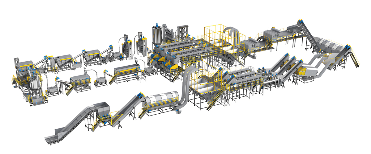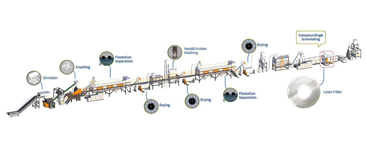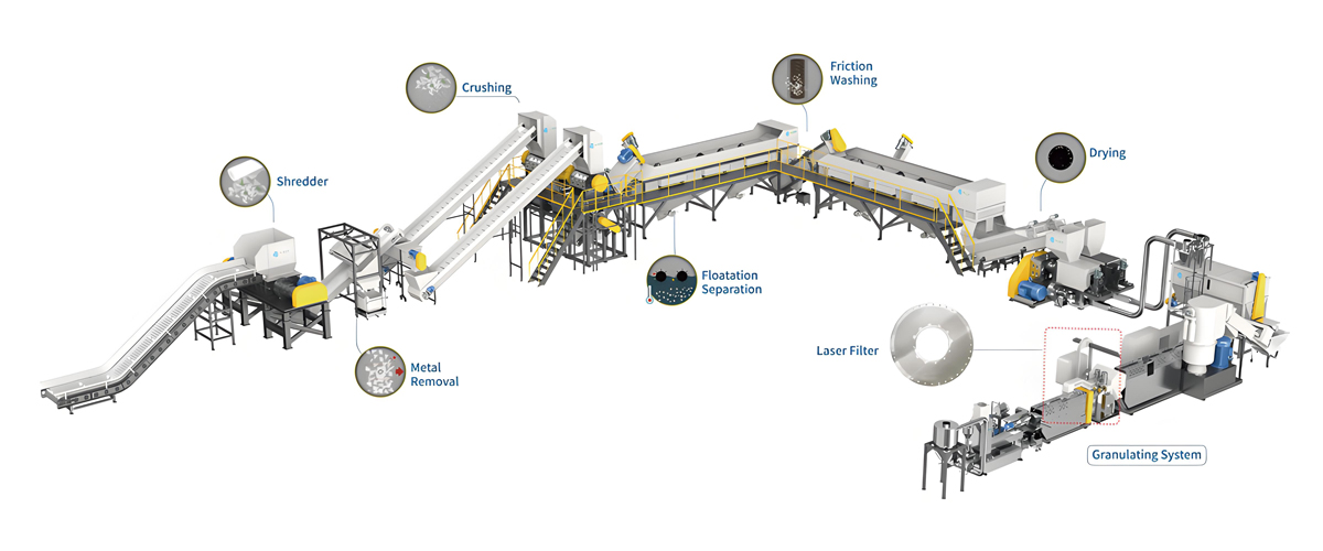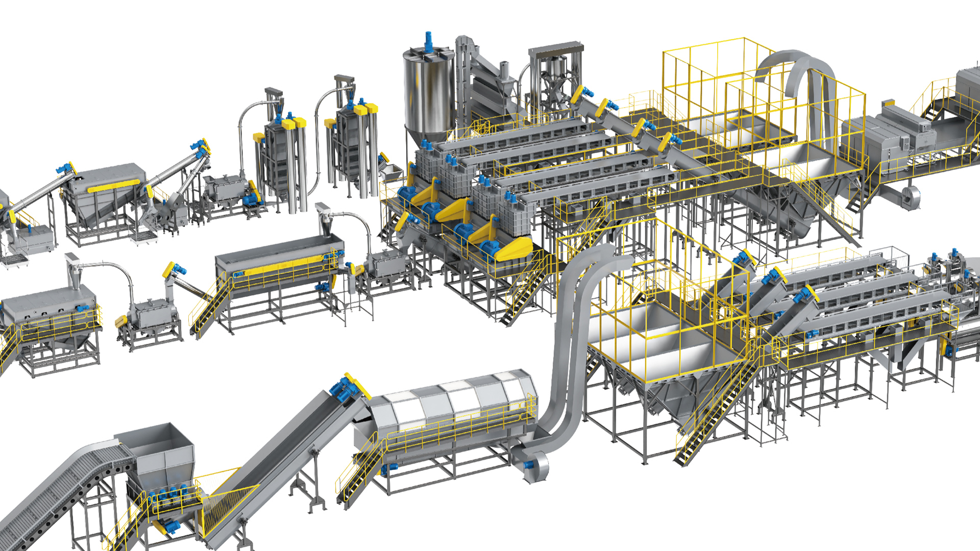

An Austrian technology plastic recycling line is defined by one decisive design choice: the material is conditioned before it ever touches the screw. Instead of dropping cold, low-density, irregular flake straight into an extruder throat and forcing it down with an auger, the Austrian route routes everything through a rotating cutter-compactor that cuts, mixes, dries, densifies and preheats the feedstock, then hands the extruder a warm, uniform, free-flowing agglomerate. That single architectural decision is why these lines have earned a reputation for low maintenance cost, and it is why the layout has been copied, licensed and refined across the global recycling equipment market for more than three decades. Polyretec, a Wanplas factory specializing in plastic recycling equipment, builds washing lines, pelletizing systems and cutter-compactor extrusion combinations that follow this engineering philosophy. This guide takes the concept apart unit by unit: the physics of the preconditioning unit, the parameter windows for the cutter-compactor and single-screw extruder, the venting and filtration systems that keep the melt clean, the specific mechanisms that suppress wear, a realistic wear-part and maintenance interval schedule, energy and throughput data across capacity classes, material-by-material process notes for polyolefins, polypropylene woven, polystyrene, polyester, polyamide and polylactic acid, quality acceptance criteria, a fault diagnosis matrix, and the compliance framework that recycled pellet buyers now demand. The goal is not marketing language about reliability. The goal is to show, mechanically and thermodynamically, why this architecture produces a lower maintenance burden than the alternatives, and where its limits lie.
What Austrian Technology Means in a Plastic Recycling Line
Austrian technology in plastic recycling refers to the integrated cutter-compactor and single-screw extruder combination, an architecture developed and industrialized in Austria and now regarded as the reference design for post-consumer and post-industrial pelletizing. The defining principle is preconditioning: converting difficult, low-bulk-density, thermally sensitive waste into a stable, dense, warm feedstock before extrusion begins. Everything downstream, from screw wear to filter life to energy consumption, follows from how well that preconditioning is executed.
The commercial landscape around this technology is dominated by a handful of Austrian names. EREMA is the most widely recognized, having built its reputation on the preconditioning unit and its associated laser filter technology. Next Generation Recyclingmaschinen, usually abbreviated NGR, developed a shredder-extruder combination in which a shredder and a single screw share a common frame and a direct material path. Starlinger, historically a woven-sack machinery builder, extended the same logic to polypropylene tapes, woven fabric and bottle-grade polyester with its recycling and decontamination systems. Each of these builders solves the same fundamental problem in slightly different ways, but they share the conviction that the extruder should never be asked to do the work of size reduction and densification.
It is worth being precise about what is Austrian and what is simply good engineering. The nationality label is a shorthand for a technology route, not a guarantee of origin. Many machines built in China, Germany, Italy, India and Turkey now implement the same route, sometimes under licence and sometimes as independent development. What matters to a buyer is whether the specific machine in front of them actually delivers the mechanical behaviour associated with the route: a genuine vortex in the cutter-compactor chamber, real temperature control on the preheated material, a tangential feed geometry that meters rather than stuffs, and a filtration system that does not require stopping the line. A machine that has a cutter-compactor bolted onto a conventional extruder but lacks temperature control and tangential metering will not deliver the maintenance advantage.
The second thing that distinguishes the route is its material tolerance. Conventional recycling lines are usually optimized for one feed geometry. A line configured for rigid regrind struggles with film, and a line configured for film cannot handle heavy rigid chunks. The preconditioning unit is far more forgiving because it normalizes geometry before feeding: film, woven fabric, sheet trim, fibre, lumps and regrind all leave the chamber as broadly similar warm agglomerate. For a recycler whose feedstock supply changes with market conditions, that adaptability translates directly into fewer changeovers, fewer configuration errors and fewer wear events caused by running material the line was never designed for.
Inside the Preconditioning Unit: Cutter-Compactor Physics
The preconditioning unit, abbreviated PCU and commonly called a cutter-compactor, is a vertical cylindrical chamber with a high-speed rotating blade disc at the bottom and a tangential discharge port connected directly to the extruder feed opening. Material entering the chamber is thrown outward and upward by the rotor, forming a toroidal vortex in which every particle is repeatedly cut, sheared against the chamber wall, and lifted back into the cutting zone. This is simultaneously a size-reduction process, a mixing process, a drying process and a heating process, and the interaction between those four functions is what makes the unit so effective.
The heating is entirely frictional. No external heaters are required in normal polyolefin operation because the rotor tip, moving at 25 to 35 metres per second, converts drive power into heat through repeated impact and shear against the material. The operator controls temperature by adjusting rotor speed and by regulating the material level in the chamber, with a thermocouple reading the bulk temperature and the control system trimming rotor speed to hold the setpoint. For polyethylene and polypropylene, the target window is 70 to 95 degrees Celsius. Below that band, densification is incomplete and the material remains fluffy. Above it, the surface of the particles begins to soften enough to cause agglomeration into lumps that bridge in the feed throat, and in extreme cases the charge can fuse into a solid mass that has to be cut out of the chamber.
Within that temperature window, three useful things happen at once. First, surface moisture evaporates and is carried away by the vented airflow, which is why a cutter-compactor line can accept film at moisture levels that would cause severe hydrolysis or bubbling in a directly fed extruder. Second, the polymer relaxes and the semi-crystalline fraction reorganizes, which slightly increases crystallinity and stiffens the particle, making it easier to cut cleanly rather than smear. Third, and most importantly for feeding, bulk density rises dramatically. Loose blown-film scrap has a bulk density of only 0.03 to 0.05 grams per cubic centimetre, essentially air with a little polymer suspended in it. After preconditioning, the agglomerate leaving the chamber typically measures 0.30 to 0.45 grams per cubic centimetre, an increase of roughly eight to twelve times.
That density increase is the mechanical foundation of the entire architecture. An extruder screw is a volumetric device: it can only convey the volume its flights enclose. When the feed material has a bulk density of 0.04 grams per cubic centimetre, the screw is transporting mostly air, output collapses, and the operator compensates by forcing material in with a stuffer, which is exactly the condition that generates wear. When the same screw receives material at 0.35 grams per cubic centimetre, the flights are properly filled, the conveying is stable, and the throughput is limited by melting capacity rather than by feeding, which is where an extruder should operate.
The tangential discharge geometry deserves attention because it is often misunderstood. The rotating material bed acts as its own feeder: the vortex presses agglomerate against the chamber wall and the tangential port simply intercepts a portion of that circulating stream. This is fundamentally different from a force feeder, which uses a separate powered auger to push material into the throat. The tangential arrangement is self-metering, it applies no external compressive force to the screw flight, and it cannot over-pack the feed zone. On larger units, a short feed screw may assist the transfer, but its function is to bridge distance rather than to compress.
Austrian Route Versus Conventional Shredder and Force Feeder
The clearest way to understand the maintenance advantage is to compare the two routes side by side on the parameters that actually generate cost. The conventional route uses a standalone shredder or granulator, a silo or conveyor, and a force feeder or crammer that stuffs the flake into the extruder throat. The Austrian route replaces all of that with a single integrated chamber. The differences show up in feeding stability, wear rate, energy, maintenance frequency and material flexibility.
| Parameter | Austrian Route: Cutter-Compactor plus Single Screw | Conventional Route: Shredder plus Force Feeder |
|---|---|---|
| Feed bulk density into screw | 0.30 to 0.45 g per cubic cm after densification; flights fully filled | 0.03 to 0.12 g per cubic cm for film and light flake; flights partly air-filled |
| Feeding stability | Self-metering tangential transfer; throughput variation typically within a few percent | Crammer-dependent; surging and bridging common with film and fibre |
| Material temperature at feed | 70 to 95 degrees Celsius, preheated and partly dried | Ambient, often with full surface moisture load |
| Screw and barrel wear driver | Reduced: less shear work in feed and compression zones, lower peak torque | Elevated: cold compaction, crammer side load, abrasive fines carried in |
| Specific energy consumption, PE film | 0.22 to 0.35 kWh per kg including preconditioning | 0.32 to 0.48 kWh per kg typical when feeding is unstable |
| Screen change behaviour | Continuous self-cleaning laser filter or backflush changer; no line stop | Manual or semi-automatic change every 2 to 8 hours on dirty feed |
| Unplanned stoppage frequency | Low; dominated by feedstock anomalies rather than machine events | Medium to high; filter blockage and feed bridging dominate |
| Film and fibre handling | Native capability; no pre-agglomeration required | Requires separate agglomerator or densifier in most cases |
| Woven polypropylene bags | Handled directly, cut and densified in one chamber | Wrapping and shaft entanglement risk in shredder |
| Rigid regrind and lumps | Handled with rotor and drive specified for the duty | Handled well; this is the conventional route’s strongest case |
| Footprint | Compact; conditioning and extrusion share one frame | Larger; separate shredder, buffer, conveyor and feeder |
| Relative capital outlay | High to Premium depending on filtration and degassing package | Medium; lower entry point, higher recurring burden |
| Relative maintenance burden | Low | Medium to High |
The comparison should not be read as a verdict that one route is universally superior. For clean, uniform, high-bulk-density rigid regrind produced in-house, a conventional shredder and gravity-fed extruder can be entirely appropriate and represents a lower entry investment. The Austrian route earns its premium when the feedstock is light, variable, filmic, printed, moist or contaminated, which describes the overwhelming majority of post-consumer streams and a large share of post-industrial film scrap. As feedstock quality declines, the maintenance gap between the two routes widens sharply.
Core Units and Engineering Parameters
An Austrian technology plastic recycling line is a chain of six functional units, each with its own parameter window: the cutter-compactor, the single-screw extruder, the degassing system, the melt filtration stage, the melt pump, and the pelletizer. Getting the parameters right on each unit individually is necessary, but the real engineering skill lies in matching them to one another so that no single stage becomes the bottleneck or the wear concentrator.
Cutter-Compactor Sizing and Rotor Configuration
Cutter-compactor chambers are specified primarily by blade disc diameter, which ranges from roughly 800 millimetres on small laboratory and pilot units to 2,200 millimetres on high-capacity industrial machines. Blade count typically runs from six to twelve, with more blades used for finer cutting on thin film and fewer, more robust blades for heavy or rigid material. Tip speed is the controlling variable and is held in the 25 to 35 metres per second band across sizes, which means rotational speed falls as diameter rises.
| Blade Disc Diameter | Typical Blade Count | Rotor Speed Range | Indicative Drive Power | Matched Throughput Class |
|---|---|---|---|---|
| 800 mm | 6 | 600 to 830 rpm | 30 to 45 kW | 150 to 300 kg per hour |
| 1,100 mm | 6 to 8 | 440 to 610 rpm | 55 to 90 kW | 300 to 500 kg per hour |
| 1,400 mm | 8 | 340 to 480 rpm | 90 to 132 kW | 500 to 800 kg per hour |
| 1,600 mm | 8 to 10 | 300 to 420 rpm | 132 to 200 kW | 800 to 1,200 kg per hour |
| 1,800 to 2,200 mm | 10 to 12 | 220 to 370 rpm | 200 to 315 kW | 1,200 to 2,000 kg per hour |
Blade material selection matters more than blade count for maintenance economics. Tool steel blades with induction-hardened edges are the baseline. Powder-metallurgy high-speed steel and tungsten-carbide-tipped variants cost more per piece but extend service life substantially on abrasive streams containing mineral filler, glass fibre, sand or residual soil. The most consequential detail is edge geometry: a square blade body with four usable cutting edges can be indexed three times before regrinding or replacement, extending the interval between full blade changes by a factor of three to four compared with a single-edge design.
Single-Screw Extruder Configuration
The extruder in an Austrian technology line is deliberately conventional in concept and precise in execution. Because the preconditioning unit has already handled densification and preheating, the screw does not need aggressive compression geometry or high shear. What it needs is a long, gentle melting profile and effective mixing, which is why length-to-diameter ratios of 30 to 36 dominate, considerably longer than the 20 to 25 typical of older recycling extruders.
| Screw Diameter | L/D Ratio | Screw Speed Range | Main Drive Power | Nominal Output, PE Film | Barrel Zones |
|---|---|---|---|---|---|
| 80 mm | 30 to 33 | 90 to 160 rpm | 75 to 110 kW | 250 to 350 kg per hour | 4 to 5 |
| 105 mm | 30 to 34 | 85 to 150 rpm | 110 to 160 kW | 420 to 550 kg per hour | 5 to 6 |
| 125 mm | 32 to 36 | 80 to 140 rpm | 160 to 250 kW | 650 to 900 kg per hour | 6 to 7 |
| 160 mm | 32 to 36 | 80 to 130 rpm | 250 to 400 kW | 1,050 to 1,400 kg per hour | 7 to 8 |
| 180 to 200 mm | 33 to 36 | 75 to 120 rpm | 400 to 630 kW | 1,600 to 2,200 kg per hour | 8 to 9 |
Barrel and screw surface treatment is a direct maintenance lever. A nitrided barrel with a nitrided screw is the economical baseline suited to clean post-industrial polyolefin. A bimetallic barrel liner combined with a hard-faced screw, using nickel-based or tungsten-carbide overlay on the flight lands, is the appropriate specification for post-consumer material carrying fines, filler or fibre, and it commonly multiplies useful service life several times over on abrasive duty. Specifying the cheaper option on abrasive feedstock is the single most common false economy in recycling line procurement, because the replacement cost of a worn screw and barrel set, plus the production lost during the change, dwarfs the initial saving.
Degassing and Volatile Removal
Devolatilization removes residual moisture, monomer, printing-ink solvent, adhesive residue and low-molecular-weight degradation products from the melt. A single vacuum vent operating at minus 0.085 to minus 0.095 megapascals gauge is standard for polyolefin film. Heavily printed film, multilayer laminate scrap and material with adhesive or coating residues justify a double vacuum arrangement, with the first vent at moderate depth and the second at full depth after a decompression and remelting section that exposes fresh melt surface.
The efficiency of degassing depends far more on melt surface renewal than on pump capacity. A vent zone with a deep-flighted decompression section, an appropriate melt seal upstream and a properly sized vacuum port will strip volatiles effectively at moderate vacuum; a poorly designed vent zone will not strip them even at maximum vacuum, and will instead push melt into the vent port. Vent flooding is a design and setpoint problem, not a pump problem. Practical measures that keep the vent clear include maintaining adequate free volume in the decompression zone, avoiding excessive screw speed relative to feed rate, and fitting a vent stuffer on lines running low-viscosity material.
Melt Filtration Architecture
Filtration is the stage where the Austrian technology route most visibly separates itself on maintenance cost, because it is the stage where conventional lines lose the most production time. Three technologies are used, often in combination.
| Filtration Type | Typical Fineness | Contaminant Discharge | Line Stop Required | Operator Attention | Best Application |
|---|---|---|---|---|---|
| Manual slide-plate changer | 150 to 400 micron | Manual screen pack removal | Yes, every change | High | Clean post-industrial, low duty |
| Continuous hydraulic double-piston changer | 80 to 200 micron | Screen pack indexing without interruption | No | Medium | General purpose polyolefin pelletizing |
| Backflush double-piston changer | 80 to 150 micron | Melt-driven reverse flush of contaminant | No | Low to Medium | Moderately contaminated post-consumer |
| Laser filter with rotating scraper | 80 to 150 micron | Continuous scraping and discharge screw | No | Low | Heavily contaminated post-consumer with paper, wood, aluminium |
| Laser filter plus piston changer in series | Coarse then 80 to 100 micron | Continuous coarse plus indexed fine | No | Low | Film-grade recyclate with strict gel and speck limits |
The laser filter deserves a specific explanation because it is the component most associated with the Austrian route. A rotating perforated disc, produced by laser drilling with precisely controlled hole geometry, is continuously swept by scraper blades. Melt passes through the holes while retained contaminant is scraped toward a discharge screw and expelled from the system as a compact plug. Because contaminant never accumulates as a filter cake, differential pressure stays close to constant, melt temperature stays stable, and there is no screen pack to change. On feedstock with two to five percent non-melting contaminant, that difference alone can eliminate several unplanned stops per shift.
Melt Pump and Pelletizing
A gear-type melt pump placed after filtration decouples extruder pressure fluctuation from die pressure. A well-tuned pump holds die pressure within roughly plus or minus 2 bar, which stabilizes pellet weight, eliminates strand diameter variation, and lets the extruder run at lower head pressure and therefore lower melt temperature and lower torque. The pump is also a maintenance asset in its own right: by absorbing pressure variation, it reduces cyclic loading on the thrust bearing of the extruder gearbox.
Three pelletizing methods are used, and the choice is dictated by polymer and target pellet quality. Water-ring pelletizing, in which the die-face cutter throws pellets into an annular water film, is the workhorse for polyolefin film recyclate and produces cylindrical to lens-shaped pellets of roughly 3 to 4 millimetres. Underwater pelletizing, where the cutting chamber is fully flooded, gives the most spherical, dust-free and uniform pellet, and is the preferred route for high-value recyclate, polyester and compounding-grade output. Strand pelletizing, where extruded strands are cooled in a water bath and chopped, remains the simplest and most economical option and is well suited to rigid materials, engineering polymers and lower throughput lines.
The Engineering Root Causes of Low Maintenance Cost
Low maintenance cost in an Austrian technology plastic recycling line is not a marketing claim; it is the arithmetic consequence of five specific engineering mechanisms, each of which removes a known failure or wear pathway. Understanding these mechanisms lets a buyer verify whether a given machine actually implements them rather than merely resembling the layout.
Mechanism one: preheating reduces shear load on the screw. The energy required to raise polyethylene from 20 degrees Celsius to melt temperature is fixed by thermodynamics. In a conventional line, all of that energy has to be supplied inside the barrel, mostly as viscous dissipation generated by the screw working against cold, stiff material. In an Austrian line, the cutter-compactor supplies the first 50 to 75 kelvin of that temperature rise through frictional heating outside the barrel, where the mechanical components involved are large, robust, easily accessed and cheaply replaced blades rather than a precision-ground screw and hardened barrel. The screw therefore operates at lower torque, lower peak flight-land pressure and lower localized temperature, all of which extend service life. This is the single largest contributor to the extended 8,000 to 20,000 hour screw and barrel inspection intervals seen on well-run lines.
Mechanism two: continuous self-cleaning filtration eliminates the most frequent stoppage. On a conventional line running post-consumer film, manual or semi-automatic screen changes every two to eight hours are normal, and each change means a stop, a pressure excursion, a purge, a quality transient and a restart. Beyond the lost production, every stop-start cycle thermally cycles the barrel, stresses the heater bands, and pushes degraded material through the die. Continuous laser filtration or backflush changing removes that entire category of event. The secondary benefits are substantial: constant back pressure means constant melt temperature, constant melt temperature means less thermal degradation, and less degradation means fewer gels, less die build-up and longer intervals between die cleaning.
Mechanism three: variable-frequency and servo drives eliminate mechanical shock. Direct-on-line starting of a large cutter-compactor rotor imposes enormous transient torque on the drive train, the belts, the shaft and the bearings. Variable-frequency drive on the rotor motor allows a controlled ramp, eliminates the starting shock, and permits the rotor speed to be trimmed continuously against measured material temperature so that the chamber never overheats or under-densifies. On the extruder side, modern drives with regenerative braking and torque limiting protect the gearbox from the shock loading that occurs when a foreign object or a cold slug reaches the screw. Servo-driven pelletizer knife positioning maintains constant blade-to-die-face contact pressure, which is the dominant variable in pelletizer knife and die-plate life.
Mechanism four: centralized and automated lubrication. Rotor bearings, extruder thrust bearings, gearbox, screen changer guides and pelletizer bearings all require scheduled lubrication. A centralized progressive lubrication system with programmed dosing removes the most common human-error failure mode in the whole plant, which is a missed grease point on a hot, noisy, dirty machine during a busy shift. Bearing failures caused by lubrication lapses are expensive not because the bearing is expensive but because the collateral damage to shafts, seals and alignment is severe and the downtime is unplanned.
Mechanism five: multi-edge indexable blades. A four-edge reversible rotor blade can be loosened, rotated to a fresh cutting edge and retightened in a fraction of the time a full replacement takes, and it can be indexed three times before the body is consumed. This extends the interval between full blade change events by roughly three to four times and converts what would be a parts-purchase event into a short labour task. Over a multi-year operating horizon, this single detail materially changes the wear-part consumption profile of the line.
Two supporting factors round out the picture. First, the compact integrated frame means fewer conveyors, fewer transfer points, fewer motors and fewer sensors, and every component that does not exist cannot fail. Second, feeding stability suppresses the surging that causes cyclic torque loading; a machine that runs at steady torque ages far more slowly than one that oscillates between 60 and 110 percent of rated load every few seconds.
Maintenance Intervals and Wear Part Life
Realistic maintenance planning requires distinguishing between inspection intervals, adjustment intervals and replacement intervals, and recognizing that all of them shift with feedstock abrasiveness. The figures below represent typical practice for clean to moderately contaminated polyolefin streams and should be shortened for material containing mineral filler, glass fibre, sand or metal fines.
| Component | Action | Typical Interval | Downtime Required | Relative Part Cost | Notes |
|---|---|---|---|---|---|
| Cutter-compactor rotor blades | Index to fresh edge | 500 to 1,500 operating hours | Short planned stop | Low | Four-edge design allows three indexing cycles before replacement |
| Cutter-compactor rotor blades | Full replacement or regrind | 2,000 to 6,000 operating hours | Half shift | Low to Medium | Carbide-tipped versions extend interval on abrasive feed |
| Chamber wall wear liner | Inspect and measure | 2,000 operating hours | Inspection only | Medium | Replaceable liner protects the chamber shell itself |
| Melt filter, continuous self-cleaning | Screen element inspection | 1,500 to 4,000 operating hours | Planned stop | Medium | No production stop for routine contaminant discharge |
| Melt filter, manual screen pack | Screen pack change | 2 to 8 operating hours on dirty feed | Line stop each time | Low per event, High cumulative | The dominant recurring cost on conventional lines |
| Screen changer seals and guides | Inspect, reseal | 4,000 to 8,000 operating hours | Half shift | Medium | Leakage past the piston indicates seal wear |
| Extruder screw and barrel | Dimensional inspection, clearance measurement | 8,000 to 20,000 operating hours | Full shift or longer | High | Bimetallic barrel and hard-faced screw extend life on abrasive duty |
| Pelletizer cutting knives | Regrind or replace | 800 to 2,000 operating hours | Short planned stop | Low to Medium | Servo contact-pressure control is the main life variable |
| Die plate | Inspect face, clean bores | 2,000 to 4,000 operating hours | Short planned stop | Medium to High | Hardened or coated faces resist knife-contact wear |
| Vacuum pump oil and filter | Change oil, replace exhaust filter | 2,000 operating hours | Short planned stop | Low | Oil condition degrades faster on printed and laminated feed |
| Melt pump | Inspect gears and bearings | 8,000 to 16,000 operating hours | Full shift | High | Clean melt upstream is the strongest determinant of life |
| Main gearbox | Oil analysis and change | 4,000 to 8,000 operating hours | Planned stop | Medium | Particle count trending predicts thrust bearing condition |
| Bearings and shaft seals | Condition monitoring, renewal | Annual inspection, renewal as indicated | Planned outage | Medium | Vibration trending gives several weeks of warning |
| Heater bands and thermocouples | Resistance check, replacement | Annual, replace on failure | Short planned stop | Low | Keep a full set of spares; failures are random |
| Centralized lubrication system | Reservoir refill, line integrity check | Monthly | None | Low | Alarm on low level and blocked line is essential |
| Pellet water circuit | Filter clean, water quality check | Weekly | None to short | Low | Fines accumulation raises knife and die wear |
Reading this table as a total workload rather than a list of parts is the useful exercise. Almost everything with a short interval is low cost and short duration, and almost everything expensive has a long interval measured in thousands of hours. That distribution is the signature of a low-maintenance-cost architecture. The conventional route inverts part of it by placing a frequent, disruptive, production-stopping event, the manual screen change, in the daily schedule.
Energy Consumption and Throughput Matrix
Specific energy consumption is the fairest way to compare recycling lines because it normalizes for size, and it is also a leading indicator of mechanical health. A line whose specific energy consumption drifts upward over months is usually telling the operator that screw and barrel clearance has increased, that filtration back pressure has risen, or that feed conditioning has degraded. The figures below cover clean, dry feedstock and represent installed power ranges together with realistic operating consumption.
| Throughput Class | Cutter-Compactor Power | Extruder Main Drive | Heating and Auxiliaries | Total Installed Power | Operating SEC, PE Film | Operating SEC, PP Woven |
|---|---|---|---|---|---|---|
| 300 kg per hour | 45 to 55 kW | 75 to 90 kW | 35 to 50 kW | 155 to 195 kW | 0.28 to 0.35 kWh per kg | 0.31 to 0.38 kWh per kg |
| 500 kg per hour | 75 to 90 kW | 110 to 132 kW | 45 to 65 kW | 230 to 287 kW | 0.26 to 0.33 kWh per kg | 0.29 to 0.36 kWh per kg |
| 800 kg per hour | 110 to 132 kW | 160 to 200 kW | 60 to 85 kW | 330 to 417 kW | 0.24 to 0.31 kWh per kg | 0.27 to 0.34 kWh per kg |
| 1,200 kg per hour | 160 to 200 kW | 250 to 315 kW | 85 to 120 kW | 495 to 635 kW | 0.23 to 0.29 kWh per kg | 0.26 to 0.32 kWh per kg |
| 2,000 kg per hour | 250 to 315 kW | 400 to 500 kW | 120 to 170 kW | 770 to 985 kW | 0.22 to 0.28 kWh per kg | 0.25 to 0.31 kWh per kg |
Three patterns in this table are worth naming. First, specific energy consumption falls as line size increases, because heat losses and fixed auxiliary loads spread over more output; this is the main technical argument for consolidating capacity into fewer larger lines rather than many small ones. Second, installed power is always substantially higher than operating consumption because motors are sized for start-up and worst-case feedstock, so a plant sizing its electrical supply on installed power will over-invest in transformers and cabling. Third, polypropylene woven material consistently sits a few hundredths of a kilowatt-hour per kilogram above polyethylene film because of its higher melting enthalpy and higher processing temperature.
Practical measures that move consumption toward the lower end of each band include insulating barrel heating zones, which typically reduces heating load noticeably; using ceramic rather than mica heater bands on high-temperature zones; running the melt pump so that the extruder can operate at lower head pressure; keeping filtration fineness no finer than the application requires; and, most importantly, holding the cutter-compactor at the correct temperature setpoint so that the extruder is not asked to make up a thermal deficit with shear. An energy management system aligned with ISO 50001 gives the measurement discipline needed to sustain those gains rather than achieve them once and lose them.
Material Compatibility Across Polymer Streams
The cutter-compactor and single-screw combination is the most materially flexible pelletizing architecture in common use, but each polymer imposes its own constraints on moisture, temperature, degassing and downstream treatment. The table below summarizes the working windows and the specific cautions that determine whether a run succeeds.
| Material | Feed Moisture Requirement | PCU Temperature | Melt Temperature | Degassing | Key Process Notes |
|---|---|---|---|---|---|
| LDPE and LLDPE film, dry | Below 2 percent | 75 to 90 C | 190 to 220 C | Single vacuum | The benchmark application; highest throughput and lowest energy of any stream |
| LDPE and LLDPE film, washed wet | Squeezer to below 8 percent before PCU | 80 to 95 C | 195 to 225 C | Single or double vacuum | A mechanical squeezer ahead of the PCU is mandatory; without it the chamber cools and densification fails |
| HDPE rigid regrind | Below 1 percent | 70 to 85 C | 200 to 230 C | Single vacuum | Higher bulk density already; PCU role shifts toward mixing, drying and metering |
| PP woven bags and raffia tape | Below 2 percent | 80 to 95 C | 210 to 240 C | Single vacuum | Cuts cleanly in the PCU where shredders suffer wrapping; watch for calcium carbonate filler abrasion |
| PS and HIPS | Below 1 percent | 60 to 75 C | 190 to 215 C | Single vacuum | Low softening point demands a lower PCU setpoint or the charge will lump; residual styrene monomer removal benefits from vacuum |
| PET sheet and thermoform trim | Crystallize and dry to below 50 ppm | Vacuum-assisted, up to 180 C in dedicated designs | 265 to 285 C | Deep double vacuum | Intrinsic viscosity retention governs everything; add solid-state polycondensation for bottle-grade output |
| PA6 and PA66 | Below 0.1 percent | 70 to 90 C | 240 to 280 C | Deep double vacuum | Strongly hygroscopic and hydrolysis-sensitive; pre-drying is not optional |
| PLA and compostable film | Below 250 ppm | 45 to 60 C | 170 to 195 C | Double vacuum | Very low glass transition means the PCU must run cool; narrow thermal window and rapid hydrolytic degradation |
| EVA and adhesive-rich film | Below 2 percent | 60 to 75 C | 170 to 200 C | Double vacuum | Tacky at low temperature; requires reduced PCU setpoint and anti-adhesion chamber surfaces |
| PP and PE fibre, nonwoven, big bag | Below 2 percent | 80 to 95 C | 200 to 235 C | Single vacuum | Fibre is the hardest geometry for conventional feeders and one of the strongest cases for this architecture |
Two material notes deserve elaboration. For washed film, the squeezer is not an optional accessory. Water entering the cutter-compactor at 20 percent moisture absorbs enormous latent heat during evaporation, which suppresses chamber temperature, prevents densification, and forces the operator to raise rotor speed and thereby drive up energy consumption and blade wear. A mechanical squeezer, essentially a short compaction extruder with a perforated barrel, brings moisture down to a level the chamber can handle thermally, and it pays for itself in energy and blade life alone.
For polyester, the fundamental issue is hydrolytic chain scission. Water present in the melt at polyester processing temperature attacks the ester linkage and reduces intrinsic viscosity irreversibly. Protecting viscosity requires crystallizing the amorphous flake so it does not agglomerate during drying, drying to a very low residual moisture level, running deep vacuum during extrusion, and minimizing residence time at temperature. Where bottle-to-bottle or food-contact output is the target, a solid-state polycondensation stage after pelletizing rebuilds molecular weight and provides the decontamination residence time that regulatory approval requires.
Pellet Quality Metrics and Test Methods
The output of a recycling line is only as valuable as the consistency the buyer can verify, and that consistency is measured with a small set of well-defined tests. A plant that runs these tests routinely and trends the results will detect mechanical degradation of the line long before it becomes a breakdown, which makes quality control a maintenance tool as well as a commercial one.
| Quality Metric | Test Method | Typical Acceptance Target | What a Failure Indicates | Test Frequency |
|---|---|---|---|---|
| Melt flow index shift versus feedstock | ISO 1133 | Within plus or minus 15 percent | Excessive shear or thermal history, or chain scission from moisture | Every lot |
| Residual moisture in pellet | Karl Fischer titration or loss on drying | Below 0.05 percent for general grades | Inadequate degassing or wet pellet dewatering | Every lot |
| Ash content | ISO 3451 | Application dependent; trend stability matters most | Filler carryover, filtration bypass or feedstock contamination | Weekly and on feedstock change |
| Tensile strength retention | ISO 527 | Above 85 to 90 percent of virgin reference | Degradation, cross-contamination or filler dilution | Monthly and on qualification |
| Gel count in cast film | Cast film gel counting per square metre | Application dependent; a stable low count is the goal | Unmelted particles, degraded material or filter bypass | Every lot for film-grade output |
| Black speck count | Visual or optical count in pressed plaque | Low and stable; rising count is the alarm | Carbonized deposit in barrel, die or adapter; degraded stagnant melt | Every lot |
| Yellowness index | Colorimeter measurement of pressed plaque | Stable within a defined band | Thermal degradation, oxidation or ink contamination | Every lot |
| Bulk density and pellet geometry | Gravimetric measurement and sieve analysis | Uniform 3 to 4 mm pellet, minimal fines and tails | Pelletizer knife wear, die-plate temperature or water flow problems | Every shift |
| Intrinsic viscosity, polyester only | Solution viscometry | Application dependent; retention is the criterion | Hydrolysis from inadequate drying or excessive residence time | Every lot |
| Odour assessment | Standardized sensory panel or headspace analysis | Acceptable for the target application | Insufficient devolatilization or organic residue in feedstock | Every lot for consumer-facing grades |
The metric most directly tied to maintenance is black speck count. A rising trend almost always means carbonized polymer is accumulating in a stagnant region, typically at a worn screw tip, in an adapter with a poor transition, behind a degraded seal, or in a die channel with a dead spot. Catching that trend early converts a future quality rejection into a scheduled cleaning task. Similarly, a widening spread in pellet geometry is usually the first observable symptom of pelletizer knife wear or uneven die-face temperature, weeks before it becomes a customer complaint.
Troubleshooting Matrix for Austrian-Type Lines
Most faults on a cutter-compactor extrusion line trace back to one of three domains: the thermal state of the chamber, the cleanliness of the melt path, or the mechanical condition of a wear part. The matrix below organizes the common symptoms by probable cause and gives a diagnostic order that moves from the cheapest check to the most disruptive.
| Symptom | Most Likely Causes | Diagnostic Sequence | Corrective Action |
|---|---|---|---|
| Gradual throughput decline at constant settings | Blade edge dulling; rising filter pressure; increased screw and barrel clearance; feedstock bulk density change | Check filter differential pressure, then motor load trend, then blade edge condition, then screw clearance | Index blades, service filtration, verify feedstock, plan screw and barrel inspection if clearance is out of tolerance |
| Material bridging in the chamber or feed throat | Chamber temperature above the material window; excessive fines; moisture spike; level control fault | Read chamber temperature, then check level sensor, then inspect feedstock moisture | Lower rotor speed or temperature setpoint, restore level control, add squeezer or pre-drying for wet feed |
| Screw slipping or intermittent feeding | Feed material too warm and tacky; feed zone temperature too high; worn feed section; insufficient chamber level | Check feed zone barrel temperature, then chamber level and temperature, then feed flight condition | Cool the feed zone, reduce chamber setpoint, restore level, inspect feed flights for wear or polishing |
| Melt pressure fluctuation exceeding plus or minus 5 bar | Feed surging; filter partially blinded; melt pump not engaged or worn; inconsistent feedstock blend | Observe pressure waveform, then check filter differential, then melt pump speed control loop | Stabilize feeding, service the filter, verify pump control, homogenize feedstock blend before the chamber |
| Pellet tails, strings or agglomerated doubles | Knife contact pressure low; blunt knives; die-face temperature too high; water flow or temperature incorrect | Check knife contact and wear, then die-face temperature, then water flow rate and temperature | Reset servo contact pressure, regrind or replace knives, adjust die heating, correct water circuit |
| Bubbles, voids or silver streaking in pellet | Insufficient vacuum; vent flooding; wet feedstock; excessive melt temperature causing degradation gas | Read vacuum gauge, then inspect vent port for melt, then verify feed moisture, then check melt temperature | Restore vacuum level, service pump and filter, correct vent zone setpoints, dry the feedstock, lower melt temperature |
| Strong residual odour in pellet | Single-stage degassing insufficient for printed or laminated feed; excessive residence time; organic residue in feedstock | Check vacuum depth, then feedstock composition, then residence time and melt temperature | Upgrade to double vacuum, improve washing upstream, reduce melt temperature and residence time |
| Rising black speck count | Carbonized deposit at worn screw tip, adapter or die; degraded seal; stagnant melt zone | Inspect die and adapter, then screw tip, then all melt-path transitions | Clean the melt path, replace worn tip or seal, eliminate dead spots, review purge procedure |
| Motor overload or torque spikes | Metal or hard foreign object in feed; cold start of chamber; excessive material level; drive tuning fault | Stop and inspect chamber, then verify metal detection upstream, then check drive ramp settings | Remove the object, install or repair metal separation, correct start sequence and drive ramp parameters |
| Excessive fines in pellet product | Blunt pelletizer knives; incorrect water temperature; excessive conveying velocity; brittle over-degraded material | Inspect knives, then water temperature, then conveying air velocity, then melt flow index shift | Service knives, tune water circuit, reduce conveying velocity, address the cause of degradation |
| Filter contaminant discharge plug too wet with polymer | Discharge screw speed too high; melt temperature too high; scraper clearance incorrect | Check discharge screw setting, then melt temperature at filter, then scraper adjustment | Reduce discharge speed, lower filter zone temperature, reset scraper clearance to specification |
| Chamber overheating and charge fusing | Temperature control loop failure; rotor speed too high for material; level too low; thermocouple drift | Verify thermocouple against a reference, then check control loop response, then review material level | Replace or recalibrate the thermocouple, retune the loop, lower rotor speed, restore correct level |
Line Layout, Utilities and Installation Planning
A recycling line that is easy to maintain on paper can become difficult to maintain in practice if the installation ignores access, utilities and material flow. Layout planning should treat the maintenance tasks in the interval table as physical operations that require space, lifting capability and safe working positions.
The critical access requirements are straightforward but frequently overlooked. Screw withdrawal needs a clear axial run at least equal to the screw length plus handling allowance, which for a 160 millimetre screw at 34 length-to-diameter ratio means well over five metres of clear space plus room for a lifting device. The cutter-compactor chamber needs overhead clearance for lid opening and blade access, and the blade indexing task needs a safe working platform rather than a ladder. The filtration unit needs lateral clearance on both sides for screen element handling and for the contaminant discharge to fall into a container that can actually be removed while the line is running. Placing the machine tight against a wall to save floor area consistently costs more in extended maintenance downtime than the floor area was worth.
Utility planning follows the installed power figures in the energy table, with the electrical supply sized on installed power but the tariff and energy budget based on operating consumption. Cooling water is required for the barrel feed-zone jacket, the gearbox oil cooler, the vacuum pump and the pellet water circuit; a closed-loop chiller with a plate heat exchanger is standard and keeps the pellet water free of the scale and biological growth that raise knife wear. Compressed air is needed for pneumatic valves, pellet conveying, and dedusting. Exhaust extraction from the cutter-compactor vent and from the vacuum pump discharge must be ducted outside and, for printed or laminated feedstock, may require treatment before discharge.
Safety design should follow EN ISO 12100 principles for machinery risk assessment and the machine should carry CE marking for the European market. The specific hazards on this equipment are well understood: the rotating blade disc requires an interlocked lid with a delayed release that prevents opening while the rotor coasts down, the melt path operates at temperatures and pressures capable of causing severe burns and requires guarding at every potential release point, and the electrical and hydraulic systems require lockout and pressure-release procedures before any intervention. A plant that documents these procedures and enforces them will also, incidentally, have better maintenance discipline overall.
Material flow into the chamber deserves as much attention as the machine itself. A metal detection and separation stage ahead of the cutter-compactor is inexpensive insurance against the single most damaging event that can occur, which is a piece of ferrous or non-ferrous metal entering the rotor. A buffer silo with level control smooths feedstock supply and prevents the chamber from running empty, which causes temperature excursions. A conveyor with adjustable speed tied to the chamber level signal is preferable to fixed-speed feeding, because it lets the control system hold the material level in the band where densification is most efficient.
Spare Parts Strategy, Operator Skill and Digital Monitoring
Maintenance cost is a function of three things: how often parts wear out, how quickly they can be replaced, and whether the failure was predicted or a surprise. The machine architecture addresses the first. The other two are organizational, and a plant that neglects them will not realize the architecture’s potential.
A sensible spare parts strategy tiers items by lead time and consequence. Tier one holds items that are consumed predictably and are cheap to stock: a complete set of rotor blades with fasteners, pelletizer knives, screen elements, heater bands, thermocouples, gaskets, seals and vacuum pump oil and filters. Tier two holds items with moderate lead time whose failure stops production: screen changer seal kits, melt pump seals, drive belts, key sensors and a spare drive unit for critical motors. Tier three covers long-lead capital spares such as a screw, a barrel section, a die plate or a gearbox, which most plants do not stock but should have identified suppliers and quoted lead times for so that a failure becomes a procurement decision rather than a crisis. Wanplas positions spare parts availability as a brand-level commitment across its factories, including an annual complimentary spare-parts allowance for line customers, and Polyretec maintains recycling-specific wear parts for the cutter-compactor and pelletizing stages.
Operator competence is the least discussed variable and one of the most influential. The parameters that most affect wear on this line, chamber temperature setpoint, material level, rotor speed and filter fineness, are all under operator control, and all of them can be set in ways that produce acceptable pellet today while quietly shortening component life. An operator who raises rotor speed to compensate for wet feedstock rather than fixing the moisture problem is trading blade life for convenience. An operator who selects a finer screen than the application needs is trading melt temperature and energy for a quality margin nobody asked for. Training should therefore cover not just how to reach a target but what each adjustment costs.
Digital monitoring turns the maintenance table from a fixed calendar into a condition-based schedule. The instrumentation worth having is modest: main drive current and torque trending, filter differential pressure, melt pressure before and after the pump, melt temperature, chamber temperature and level, vacuum level, gearbox oil temperature, and vibration on the rotor and extruder thrust bearing. Trending these signals reveals the slow drifts that matter. Rising specific energy consumption at constant throughput indicates clearance or filtration problems. Rising filter differential pressure at constant feedstock indicates element fouling. Rising vibration amplitude at a bearing frequency indicates a bearing approaching the end of its life, usually with weeks of warning. None of this requires an elaborate platform; a data historian with alarm bands and a weekly review meeting captures most of the value.
The final organizational element is a purge and shutdown discipline. Most black-speck and gel problems originate in material that sat hot during an unplanned stop. A documented procedure that purges the melt path with a suitable purging compound before any extended stop, drops barrel temperatures in a controlled sequence, and specifies the restart ramp will prevent a large share of the quality faults that operators otherwise attribute to feedstock.
Compliance, Certification and Circular Economy Requirements
Recycled pellet is no longer sold on specification alone; it is sold on documented compliance, and the equipment and process must be able to support the claims made about the output. For a recycler investing in an Austrian technology plastic recycling line, the regulatory framework should be understood before the line is specified, because retrofitting decontamination capability is far more expensive than including it.
| Framework | Scope | Relevance to the Recycling Line |
|---|---|---|
| EU Single-Use Plastics Directive | Restrictions on specified single-use items and recycled-content obligations for beverage bottles | Drives demand for high-quality recyclate and creates the market pull for food-grade capable lines |
| EU 2022/1616 | Regulation on recycled plastic materials and articles intended to contact food | Defines the authorization pathway for recycling processes producing food-contact recyclate |
| EFSA process evaluation | Scientific assessment of decontamination efficiency of a specific recycling process | Requires documented residence time, temperature and vacuum conditions; the equipment must be able to hold and prove them |
| EuCertPlast | European certification of post-consumer plastic recyclers | Audits traceability of input, process control and output quality across the plant |
| RecyClass | Recyclability evaluation and recycled-content traceability certification | Supports recycled-content claims that brand owners increasingly require in supply contracts |
| Global Recycled Standard | Chain-of-custody standard for recycled content, widely used in textiles and packaging | Requires documented mass balance from feedstock intake through pelletizing to dispatch |
| ISO 14001 | Environmental management systems | Covers wastewater, emissions, waste contaminant disposal and continual improvement obligations |
| ISO 15270 | Guidelines for the recovery and recycling of plastics waste | Provides the terminology and process framework used in tenders and customer specifications |
| ISO 50001 | Energy management systems | Formalizes the specific energy consumption monitoring that also serves as predictive maintenance data |
| ISO 1133, ISO 3451, ISO 527 | Melt flow rate, ash content and tensile property test methods | The measurement basis for the quality acceptance criteria written into pellet supply agreements |
| CE marking and EN ISO 12100 | Machinery safety conformity and risk assessment methodology | Mandatory for placing the equipment on the European market; governs guarding, interlocks and documentation |
The commercial logic behind this framework is worth stating plainly. Brand owners have made public recycled-content commitments and are contractually obliged to meet them, which means they need recyclate that is documented, traceable and consistent rather than merely cheap. That shift rewards recyclers who can demonstrate process control, and process control is easier to demonstrate on a line whose parameters are stable, instrumented and recorded. An architecture that holds melt pressure within a few bar, holds filtration continuously without stopping, and logs specific energy consumption per lot produces the audit trail these certifications require almost as a by-product.
Relative Cost of Ownership Over a Ten-Year Horizon
Comparing recycling line investments only on purchase price systematically misleads, because the purchase price is a one-time event while wear parts, energy, downtime and quality rejection recur every year for the life of the asset. The table below compares three architectures on a qualitative relative scale across the cost categories that matter, using descriptive labels rather than figures because actual values depend heavily on local energy tariffs, labour rates, feedstock quality and utilization.
| Cost Category | Austrian Route with Laser Filter | Austrian Route with Piston Changer | Conventional Shredder and Force Feeder |
|---|---|---|---|
| Initial capital outlay | Premium | High | Medium |
| Installation and commissioning effort | Medium | Medium | High |
| Energy cost per tonne of pellet | Low | Low | Medium to High |
| Screw and barrel replacement burden | Low | Low | High |
| Filtration consumable cost | Medium | Medium | High |
| Cutting tool and blade cost | Low | Low | Medium |
| Unplanned downtime cost | Low | Low to Medium | High |
| Labour requirement per shift | Low | Medium | High |
| Quality rejection and reprocessing | Low | Low to Medium | Medium to High |
| Feedstock flexibility value | Very High | Very High | Medium |
| Suitability for contaminated post-consumer feed | Very High | Medium to High | Low to Medium |
| Total cost of ownership over ten years | Low | Low to Medium | High |
The pattern is consistent: the Austrian route front-loads cost into the purchase and then runs cheaply, while the conventional route saves at purchase and pays continuously. The crossover point depends almost entirely on utilization and feedstock quality. A plant running one shift on clean in-house scrap may never reach the crossover, and for that plant the conventional route is genuinely the right answer. A plant running three shifts on purchased post-consumer material will typically cross over well within the first years of operation and will keep accumulating advantage for the remaining asset life. The decision, in other words, is not about which technology is better in the abstract but about where a specific operation sits on the utilization and contamination axes.
One category in the table is easy to underweight and shouldn’t be: feedstock flexibility value. Recyclers operate in a market where feedstock availability and composition shift with collection policy, seasonal patterns and competing demand. A line that can accept film this quarter and woven bags next quarter without mechanical modification has an option value that never appears on a maintenance ledger but frequently determines whether a plant can keep running at full utilization when its preferred feedstock becomes scarce or expensive.
How Polyretec Engineers Austrian-Technology Recycling Lines
Polyretec, a Wanplas factory dedicated to plastic recycling equipment, builds washing lines, squeezer and dewatering systems, cutter-compactor extrusion combinations and pelletizing lines that implement the engineering principles described in this article. The design philosophy is to specify each unit for the actual feedstock rather than to a generic catalogue configuration, because the difference between a low-maintenance line and a high-maintenance one is almost always a specification decision made before the machine was built.
In practice, that means a project starts with feedstock characterization: polymer identity and blend consistency, contamination type and level, incoming moisture, bulk density, geometry and abrasive content. Those parameters determine rotor diameter and blade count, blade material and edge geometry, chamber drive power, whether a squeezer is required ahead of the chamber, screw geometry and surface treatment, whether a bimetallic barrel is justified, single or double degassing, filtration technology and fineness, whether a melt pump is warranted, and which pelletizing method matches the target pellet. Each of those choices moves the maintenance profile, and getting them right at the specification stage is far cheaper than correcting them later.
Because Polyretec sits within the Wanplas brand and its network of specialized factories, a recycling line project can draw on adjacent capabilities without leaving the group. Where a compounding step is required, for example when the recyclate needs filler, impact modifier or colour masterbatch added during pelletizing, Wanplas’s Kerke factory supplies co-rotating twin-screw compounding extruders that integrate downstream of Polyretec washing and preconditioning systems. Where the recycled pellet feeds directly into a converting operation, other Wanplas factories cover pipe and profile extrusion, film and sheet extrusion, extrusion blow moulding, injection blow moulding and polyester bottle blowing, which makes it practical to validate recyclate performance on the actual downstream process rather than only in a laboratory. That vertical view is consistent with the Wanplas mission to warm global customers with China plastic machinery, and it is particularly useful for recyclers who are qualifying a new grade for a specific end application.
Support after commissioning is where maintenance cost is ultimately won or lost. Wanplas maintains a brand-level spare parts commitment that includes an annual complimentary allowance of wear parts for line customers, and Polyretec stocks the recycling-specific consumables that determine uptime: rotor blades in standard and abrasion-resistant grades, screen elements across the common fineness range, pelletizer knives, die plates, seals and heater sets. Combined with remote diagnostics on the control system and structured operator training that covers the cost consequences of parameter choices, that support turns the architectural advantage described in this article into a measurable operating result.
Frequently Asked Questions
What exactly is an Austrian technology plastic recycling line?
It is a recycling and pelletizing architecture in which a cutter-compactor, also called a preconditioning unit, is directly coupled to the feed opening of a single-screw extruder. The rotating blade disc cuts, mixes, dries and preheats the material to roughly 70 to 95 degrees Celsius, raising bulk density from around 0.03 to 0.05 grams per cubic centimetre for loose film up to 0.30 to 0.45 grams per cubic centimetre, then feeds the warm agglomerate into the screw at a steady, self-metered rate. The concept was developed and industrialized in Austria and is associated with builders such as EREMA, NGR and Starlinger, and it is now implemented worldwide by manufacturers including Polyretec.
Why does a cutter-compactor reduce screw and barrel wear?
The preconditioning unit performs size reduction, densification, drying and preheating outside the barrel, so the screw receives a warm, uniform, free-flowing agglomerate rather than cold, low-density flake. Less shear energy has to be generated inside the feed and compression zones, peak torque is lower and steadier, and no crammer imposes side loading on the screw. Field practice on well-run polyolefin lines commonly places screw and barrel inspection intervals in the 8,000 to 20,000 operating hour range, with bimetallic barrels and hard-faced screws extending that further on abrasive feedstock.
How much energy does an Austrian technology recycling line consume?
For clean, dry LDPE or LLDPE film, specific energy consumption typically falls between 0.22 and 0.35 kilowatt-hours per kilogram measured across the main drive, cutter-compactor and heating. Larger lines sit toward the lower end because fixed losses spread over more output. Polypropylene woven material runs a few hundredths higher because of greater melting enthalpy, and moist or heavily printed feedstock pushes consumption toward the top of the band or beyond.
Is a laser filter better than a hydraulic double-piston screen changer?
A laser filter with a rotating scraper and continuous discharge is better for heavily contaminated post-consumer streams containing paper, wood, aluminium or higher-melting cross-contamination, because it removes contaminant continuously without stopping the line or requiring operator intervention. A continuous hydraulic double-piston backflush changer is more economical and entirely adequate for cleaner post-industrial material. Many high-specification lines run both in series, using the laser filter for coarse protection and the piston changer as the fine polishing stage at 80 to 100 microns.
What filtration fineness should a recycling line target?
Most polyolefin pelletizing lines operate in the 80 to 150 micron range. Film-grade recyclate destined for thin blown film generally needs the finer end near 80 to 100 microns to keep gel and black-speck counts acceptable, while injection-grade or pipe-grade output tolerates 120 to 150 microns. Specifying finer filtration than the application requires raises back pressure, melt temperature and screen consumption while reducing throughput, so the fineness should be set by the end use rather than by instinct.
How often do cutter-compactor blades need attention?
On a clean polyolefin film stream, rotor blades typically run 500 to 1,500 operating hours before being indexed to a fresh cutting edge, with full replacement or regrinding at roughly 2,000 to 6,000 hours. Four-edge reversible blade bodies extend the interval between full replacements by about three to four times compared with single-edge designs. Feedstock containing sand, mineral filler or glass fibre shortens all of these intervals substantially, which is when carbide-tipped or powder-metallurgy blades become worthwhile.
Can the same line process film, woven bags and rigid regrind?
Yes, and that flexibility is one of the strongest arguments for the architecture. The cutter-compactor handles loose film, woven polypropylene bags, sheet trim, fibre and edge trim natively, and it also accepts rigid regrind when the rotor geometry and drive power are specified for that duty. What changes between materials is rotor speed, chamber temperature setpoint, screw geometry and filtration fineness, not the fundamental machine layout, so changeover is a recipe change rather than a mechanical rebuild.
Does the technology work for PET, or is it only for polyolefins?
It works for polyester, but polyester demands process control that polyolefins do not. Intrinsic viscosity is protected by crystallizing and drying the flake before extrusion, running deep double vacuum degassing at minus 0.085 to minus 0.095 megapascals, and minimizing residence time at 265 to 285 degrees Celsius. For bottle-to-bottle or food-contact output, a solid-state polycondensation stage after pelletizing rebuilds molecular weight and provides the decontamination residence time that an EFSA-evaluated process under EU 2022/1616 requires.
What is the realistic maintenance workload of such a line?
Daily work reduces to lubrication system checks, blade condition inspection, filter discharge inspection, and pelletizer knife and water quality checks, most of which can be performed while the line runs. Heavy interventions such as screw and barrel inspection, gearbox overhaul and bearing and seal renewal are planned annual or multi-year events. The decisive structural difference against conventional lines is that continuous self-cleaning filtration removes the manual screen change, which is the single most frequent production-stopping event on a conventional recycling line.
Which certifications matter for recycled pellet buyers?
For European food-contact applications the governing framework is EU 2022/1616 together with an EFSA evaluation of the specific recycling process. For general recycled-content claims, EuCertPlast, RecyClass and the Global Recycled Standard are the certifications buyers most frequently request. On the operational side, ISO 14001 for environmental management, ISO 15270 for plastics waste recovery guidance and ISO 50001 for energy management are increasingly written into supply agreements, and the machinery itself must carry CE marking with a risk assessment consistent with EN ISO 12100.
How do I know whether a machine genuinely implements the Austrian route?
Check four things. First, is chamber temperature actually measured and controlled, with rotor speed trimmed against it, or is the chamber simply a densifier running open loop? Second, is the transfer to the extruder tangential and self-metering, or is there a powered stuffer applying compressive force? Third, does the filtration system discharge contaminant continuously without a line stop? Fourth, are the drives variable-frequency with controlled ramping rather than direct-on-line? A machine that answers yes to all four will deliver the maintenance behaviour described here; one that answers no to several will not, regardless of how similar it looks.
What is the most common specification mistake buyers make?
Choosing a nitrided screw and barrel for abrasive post-consumer feedstock in order to reduce the purchase price. Mineral filler, glass fibre, residual sand and metal fines wear a nitrided surface far faster than a bimetallic barrel with a hard-faced screw, and the cost of a premature screw and barrel replacement, plus the production lost during the change and the quality drift as clearance grows, greatly exceeds the initial saving. The second most common mistake is omitting the squeezer ahead of the cutter-compactor on washed film lines, which quietly raises energy consumption and blade wear on every hour of operation.
Conclusion
An Austrian technology plastic recycling line achieves low maintenance cost through mechanism rather than marketing. By moving size reduction, drying, densification and preheating out of the extruder barrel and into a cutter-compactor that raises bulk density from 0.03 to 0.05 up to 0.30 to 0.45 grams per cubic centimetre and delivers material at 70 to 95 degrees Celsius, the architecture removes the two dominant wear drivers in recycling extrusion: cold compaction against the screw and forced feeding under side load. Continuous self-cleaning filtration at 80 to 150 microns eliminates the manual screen change that dominates the unplanned downtime schedule on conventional lines. Variable-frequency and servo drives remove mechanical shock, centralized lubrication removes the most common human-error failure, and four-edge indexable blades extend the interval between full blade replacements by three to four times. The result is a maintenance profile in which the frequent tasks are cheap and quick while the expensive tasks fall at 8,000 to 20,000 hour intervals, and in which specific energy consumption sits in the 0.22 to 0.35 kilowatt-hours per kilogram band for polyethylene film. The architecture is not universally optimal; a single-shift operation processing clean in-house rigid regrind may be better served by a conventional line at lower capital outlay. But for any recycler handling film, woven material, fibre, printed or contaminated post-consumer feedstock at meaningful utilization, the total cost of ownership case is clear and it strengthens as feedstock quality declines. Polyretec, a Wanplas factory, specifies and builds these lines around the actual feedstock rather than a catalogue configuration, because the difference between a low-maintenance line and a high-maintenance one is decided at the specification stage, long before the first blade is indexed.